2-6 Connections Models 2510 and 2510-AT User’s Manual
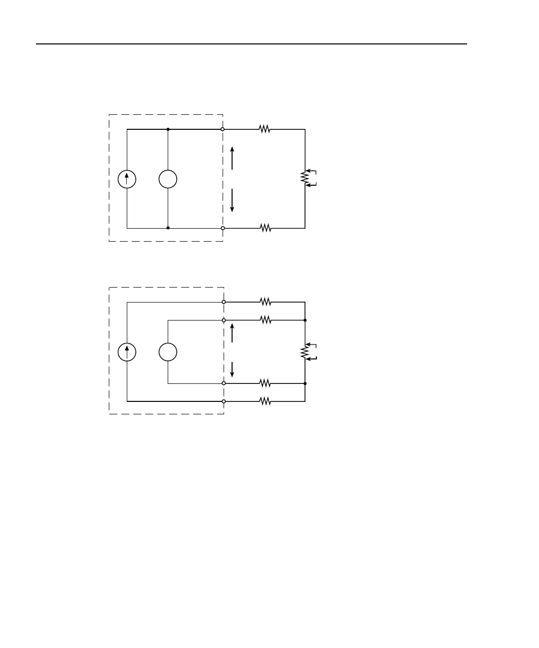
Figure 2-4
Sensing methods
4-wire sensing
Due to the limitations of the 2-wire method, the 4-wire connection method shown in
Figure 2-4B is recommended for sensors <1kΩ. With this configuration, the test current (I)
is forced through the thermistor through the F+ and F- wires, while the voltage across the
thermistor is measured through a second set of wires connected to the S+ and S- (sense)
terminals. Although some small current may flow through the sense wires, it is usually
negligible and can generally be ignored for all practical purposes. Since the voltage drop
across the sense wires is negligible, the voltage measured by the Model 2510 is essentially
the same as the voltage across the thermistor (V
M
≅ V
T
), and more accurate resistance and
temperature measurements result from the following resistance calculation:
V
V
I
I
Rw
Rw
Rw
Rw
Rw
Rw
F+
F+
F-
F-
Thermistor
Thermistor
INPUT
INPUT
Model 2510
Model 2510
R
T
M
M
A. 2-Wire Connections
B. 4-Wire Connections
S+
S-
R
T
V
T
V
T
R
T
V
T
I
-------=