HW 3/13/02
Rev. B
2510 TEC SourceMeter
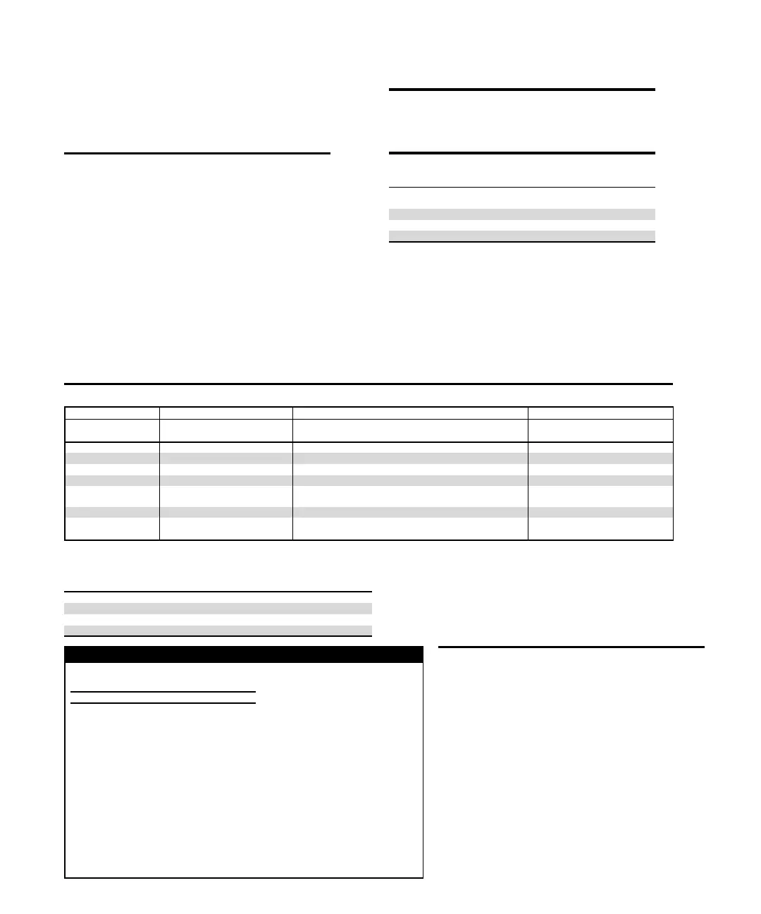
THERMISTOR MEASUREMENT ACCURACY
14
Nominal
Thermistor
Accuracy vs.Temperature
Resistance 0°C 25°C 50°C 100°C
100 Ω 0.021°C 0.035°C 0.070°C 0.27°C
1kΩ 0.015°C 0.023°C 0.045°C 0.18°C
10 kΩ 0.006°C 0.012°C 0.026°C 0.15°C
100 kΩ 0.009°C 0.014°C 0.026°C 0.13°C
OPEN/SHORTED ELEMENT DETECTION
SOFTWARE LINEARIZATION FOR THERMISTOR AND RTD
COMMON MODE VOLTAGE: 30VDC.
COMMON MODE ISOLATION: >10
9
Ω, <1000pF
MAX.VOLTAGE DROP IN INPUT FORCE LEADS: 1 volt.
MAX. SENSE LEAD RESISTANCE: 100Ω for rated accuracy.
SENSE INPUT IMPEDANCE: > 1·10
8
Ω.
GENERAL
NOISE REJECTION:
SPEED NPLC CMRR
12
Normal 1.00 90 dB
SOURCE OUTPUT MODES: Fixed DC level.
PROGRAMMABILITY: IEEE-488 (SCPI-1995.0), RS-232, 3 user-definable power-up states plus
factory default and *RST.
POWER SUPPLY: Nominal 100 to 240VAC rms, 50–60Hz, 90VA.
WARRANTY: 1 year.
EMC: Conforms to European Union Directive 89/336/EEC, EN 61326-1.
SAFETY: Conforms to European Union Directive 73/23/EEC, EN 61010-1.
VIBRATION: MIL-PRF-28800F Class 3 Random Vibration.
WARM-UP: 1 hour to rated accuracies.
DIMENSIONS, WEIGHT: 89mm high × 213 mm wide × 370mm deep (3
1
⁄
2
in × 8
3
⁄
8
in × 14
9
⁄
16
in).
Bench configuration (with handle & feet): 104mm high × 238mm wide × 370mm deep (4
1
⁄
8
in
× 9
3
⁄
8
in × 14
9
⁄
16
in). Net Weight: 3.8kg (8.38 lbs).
ENVIRONMENT: Operating: 0°–50°C, 70% R.H. up to 35°C. Derate 3% R.H./°C, 35°–50°C.
Storage: –25° to 65°C
The Model 2510 Thermoelectric Cooler Controller is designed to:
• control the power to the TEC to maintain a constant temperature,
current, voltage, or thermistor resistance
• measure the resistance of the TEC
• software PID loop
TEC OUTPUT SPECIFICATIONS
OUTPUT RANGE: ±10 VDC at up to ±5 ADC.
OUTPUT RIPPLE: <5mV rms.
5
AC RESISTANCE EXCITATION: ±(9.6mA + 190µA).
10, 11
TEC MEASUREMENT SPECIFICATIONS
FUNCTION 1 Year, 23°C ±5°C
Operating
Resistance
1, 6,7, 8
±(2.0% of rdg + 0.1Ω)
Operating Voltage
1, 6
±(0.1% of rdg + 4mV)
Operating Current
6
±(0.4% of rdg + 8mA)
AC Resistance
1, 13
±(0.10% of rdg + 0.02Ω)
OPEN SHORTED THERMOELECTRIC DETECTION
LOAD IMPEDANCE: Stable into 1µF typical.
COMMON MODE VOLTAGE: 30VDC maximum.
COMMON MODE ISOLATION: >10
9
Ω, <1500pF.
MAX. SENSE LEAD RESISTANCE: 1Ω for rated accuracy.
MAX. FORCE LEAD RESISTANCE: 0.1Ω.
THERMAL FEEDBACK ELEMENT SPECIFICATIONS (1 Year, 23°C ±5°C)
Sensor Type RTD Thermistor Solid State
Current Voltage
100 Ω 1 kΩ 100 Ω 1 kΩ 10 kΩ 100 kΩ Output (I
SS
) Output (V
SS
)
Excitation
9
2.50 mA 833 µA 2.5 mA 833 µA 100 µA 33 µA +13.5V 2.5 mA
Compliance 833 µA max 833 µA 15.75 V max
Nominal Resistance Range
0–250 Ω 0-2.50 kΩ 0–1 kΩ 0–10 kΩ 0–80 kΩ 0–200 kΩ
Excitation Accuracy ±2.9% ±2.9% ±2.9% ±2.9% ±2.9% ±2.9% ±12% ±2.9%
Nominal Sensor
Temperature Range –50° to +250°C –50° to +250°C –50° to +250°C –50° to +250°C –50° to +250°C –50° to +250°C –40° to +100°C –40° to +100°C
Sensor Coefficients α, β, δ α, β, δ A, B, C A, B, C A, B, C A, B, C Slope & offset Slope & offset
Measurement Accuracy
±(% rdg + offset) 0.04 + 0.07 Ω 0.04 + 0.4 Ω 0.04 + 0.07 Ω
1
0.04 + 0.4 Ω
1
0.02 + 3 Ω
1
0.04 + 21 Ω 0.03 + 100 nA 0.03 + 500 µV
CONTROL SYSTEM SPECIFICATIONS
SET: Constant Peltier Temperature
Constant Peltier Voltage
Constant Peltier Current
Constant Thermistor Resistance
CONTROL METHOD:
Programmable software PID loop.
Proportional, Integral, and Derivative gains independently program-
mable.
SETPOINT SHORT TERM STABILITY: ±0.005°C rms.
2, 3
SETPOINT LONG TERM STABILITY: ±0.01°C.
2, 4
SETPOINT RANGE: –50°C to 225°C.
OVER TEMPERATURE LIMIT: 250°C max.
UNDER TEMPERATURE LIMIT: –50°C max.
SETPOINT RESOLUTION: 0.001°C, 1mV, 100µA, 0.01% of nominal (25°C)
thermistor resistance.
HARDWARE CURRENT LIMIT: 1.0A to 5.25A ±5%.
SOFTWARE VOLTAGE LIMIT:±0.5 to 10.5V ±5%.
NOTES
1 With remote voltage sense.
2 With 10kΩ thermistor as sensor.
3 Short term stability is defined as
24 hours with Peltier and Model
2510 at 25°C ±0.5°C.
4 Long term stability is defined as
30 days with Peltier and Model
2510 at 25°C ±0.5°C.
5 10Hz to 10MHz measured at 5A
output into a 2Ω load.
6 Common mode voltage = 0V
(meter connect enabled, connects
Peltier low output to thermistor
measure circuit ground). ±(0.1%
of rdg + 0.1Ω) with meter connect
disabled.
7 Resistance range 0Ω to 20Ω for
rated accuracy.
8 Current through Peltier > 0.2A.
9 Default values shown, selectable
values of 3µA, 10µA, 33µA, 100µA,
833µA, 2.5mA. Note that tempera-
ture control performance will
degrade at lower currents.
10 AC Ohms is a dual pulsed meas-
urement using current reversals
available over bus only.
11 @23°C ±5°C.
12 For 1kΩ unbalance in LO lead.
Minimum amplifier specification.
13 Resistance range 0Ω to 100Ω for
rated accuracy.
14 Accuracy figures represent the
uncertainty that the Model 2510
may add to the temperature
measurement, not including ther-
mistor uncertainty. These accura-
cy figures are for thermistors with
typical A, B, C constants.