Section 2: General operation Model 2657A High Power System SourceMeter® Instrument Reference Manual
2-90 2657A-901-01 Rev. B/December 2012
RS-232 connections
Connect the RS-232 serial port of the Model 2657A to the serial port of a computer using a straight-
through RS-232 cable terminated with DB-9 connectors. Do not use a null modem cable. The serial
port uses the transmit (TXD), receive (RXD), CTS and RTS (if flow control is enabled), and signal
ground (GND) lines of the RS-232 standard. The connector location is shown in Remote
Communication interfaces (on page 2-79).
If your computer uses a DB-25 connector for the RS-232 interface, you will need a standard cable or
adapter with a DB-25 connector on one end and a DB-9 connector on the other. An RS-232 cable is
available from the Keithley Instruments website
(http://www.keithley.com).
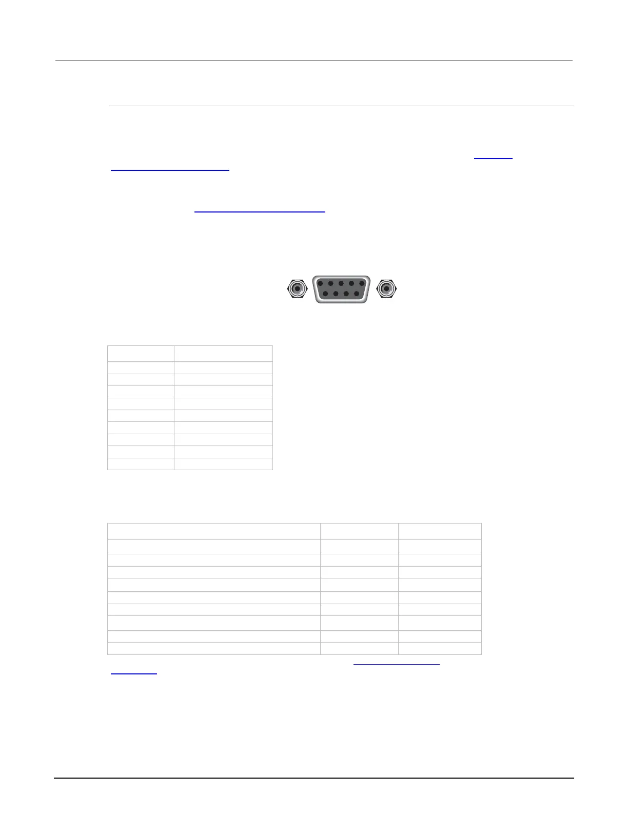
Figure 29: RS-232 interface connector
RS-232 connector pinout
Pin number Description
1 Not used
2 TXD, transmit data
3 RXD, receive data
4 Not used
5 GND, signal ground
6 Not used
7 RTS, ready to send
8 CTS, clear to send
9 Not used
The following table provides pinout identification for the 9-pin (DB-9) or 25-pin (DB-25) serial port
connector on the computer.
Computer serial port pinout
Signal* DB-9 pin number DB-25 pin number
DCD, data carrier detect 1 8
RXD, receive data 2 3
TXD, transmit data 3 2
DTR, data terminal ready 4 20
GND, signal ground 5 7
DSR, data set ready 6 6
RTS, request to send 7 4
CTS, clear to send 8 5
RI, ring indicator 9 22
* The Model 2657A does not use all RS-232 signals. See the topic Flow control and signal
handshaking (on page 2-89).
9876
54321
Rear Panel Connector
RS-232