Model 2657A High Power System SourceMeter® Instrument Reference Manual Section 3: Functions and features
2657A-901-01 Rev. B/December 2012 3-81
Digital I/O lines
The port provides 14 digital I/O lines. Each output is set high (+5 V) or low (0 V) and can read high or
low logic levels. Each digital I/O line is an open-drain signal.
+5 V output
The digital I/O port provides a +5 V output that is used to drive external logic circuitry. Maximum
current output for these lines is 250 mA. This line is protected by a self-resetting fuse with a one hour
recovery time.
Interlock line
At no time should you bypass the interlock feature of the Model 2657A. Safe operation requires a
separate interlock circuit that meets the requirements of the application to reliably protect the
operator from exposed voltages. Bypassing the interlock could expose the operator to hazardous
voltages that could result in personal injury or death.
The Model 2657A interlock (INT) line of the digital I/O can be used with a switch in the test fixture or
component handler. With proper use, power is removed from the DUT when the lid of the fixture is
opened. See Operation
(on page 3-85) for more details.
Use interlock cable assembly CA-558 to connect the Model 2657A interlock to either a Model 8010
High Power Device Test Fixture or to the Model 2657A-LIM-3 LO Interconnect Module (refer to the
connection information supplied with the device).
Digital I/O configuration
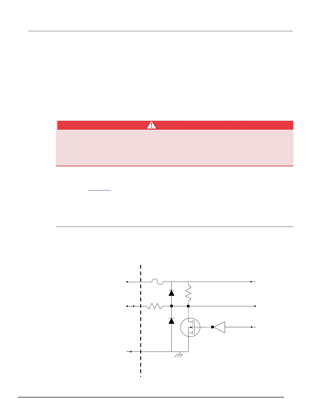
The following figure shows the basic configuration of the digital I/O port. Writing a 1 to a line sets that
line high (~ +5 V). Writing a 0 to a line sets that line low (~0 V). Note that an external device pulls an
I/O line low by shorting it to ground, so that a device must be able to sink at least 480 μA per I/O line.
Figure 66: Digital I/O port configuration
WARNING
+5 VD
5.1 kΩ
100 Ω
+5 V pins
(on DIGITAL I/O connector)
Solid state
fuse
DIGITAL I/O pin
(on DIGITAL I/O connector)
Read by firmware
Rear panel
Written by firmware
GND pin
(on DIGITAL I/O connector)