Section 4: Theory of operation Model 2657A High Power System SourceMeter® Instrument Reference Manual
4-12 2657A-901-01 Rev. B/December 2012
I-source operating boundaries
Model 2657A I-source operating boundaries
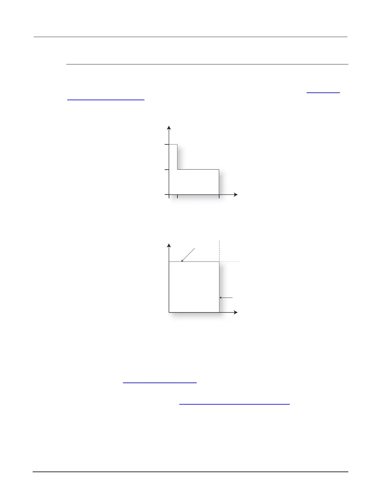
The following figure shows the operating boundaries for the I-source. Only the first quadrant of
operation is shown; operation in the other three quadrants is similar with respect to the Continuous
power operating boundaries (on page 4-4).
Figure 77: Models 2657A I-source boundaries
The first graph in the figure, labeled "A: Output characteristics," shows the output characteristics for
the I-source. As shown, Model 2657A instruments can continuously output up to +120 mA at 1.5 kV
or up to 20 mA at 3.0 kV.
The second graph in the figure, labeled "B: Limit lines," shows the operating area of the I source on a
given range. The maximum current source value line shows the maximum possible source current for
the selected current range. The voltage compliance limit line represents the actual compliance limit
that is in effect (see Compliance limit principles
(on page 4-2)). These lines are boundaries that
represent the operating limits of the System SourceMeter instrument for this quadrant of operation.
The operating point can be anywhere inside (or on) these lines. The boundaries for the other
quadrants are similar with respect to the Continuous power operating boundaries
(on page 4-4).
V-measure
120 mA
20 mA
1.5 KV
3.0 KV
A: Output characteristics
B: Limit lines
I-source
Source I
Limit V
Voltage
compliance
limit line
Maximum current
source value line
 Loading...


