Model 2657A High Power System SourceMeter® Instrument Reference Manual Section 4: Theory of operation
2657A-901-01 Rev. B/December 2012 4-19
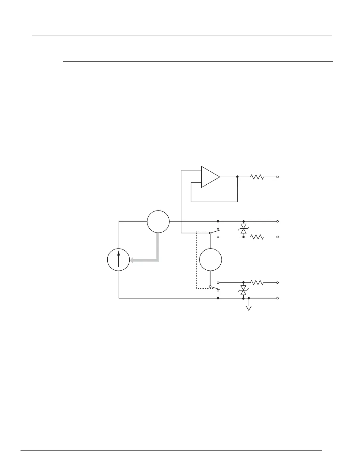
Source I
When the instrument is configured to source current (I-source), as shown in the figure below, the
instrument functions as a high-impedance current source with voltage limit capability and can
measure current (I-meter) or voltage (V-meter).
For 2-wire local sensing, voltage is measured at the input/output terminals of the instrument. For 4-
wire remote sensing, voltage is measured directly at the device under test (DUT) using the sense
terminals. This eliminates any voltage drops that may be in the test leads or connections between the
instrument and the DUT.
The current source does not require or use the sense leads to enhance current source accuracy.
However, if the instrument is in 4-wire remote sense mode, the instrument may reach limit levels if the
sense leads are disconnected. With 4-wire remote sensing selected, the sense leads must be
connected or incorrect operation will result.
Figure 85: Source I configuration
Remote
SENSE HI
HI
Remote
LO
I-source
x1
V-meter
SENSE LO
Local
Local
GUARD
+
–
I-meter
1
2
2
2
1
Feedback
NOTES: 1. This represents a protection circuit. Do not apply more than 3030 V
between HI and SENSE HI. To maintain optimal operation and obtain
accurate measurements, the maximum voltage between HI and
SENSE HI should be no more than 3 V. This limit also applies to the
maximum voltage between LO and SENSE LO.
2. Approximately 80 kΩ.
A
V