Section 2: General operation Model 2657A High Power System SourceMeter® Instrument Reference Manual
2-46 2657A-901-01 Rev. B/December 2012
Guard voltage can be hazardous. With an unguarded device under test (DUT) connection, terminate
the guard before the end of the cable. Refer to High-voltage triaxial cable termination (on page 2-
44) for details.
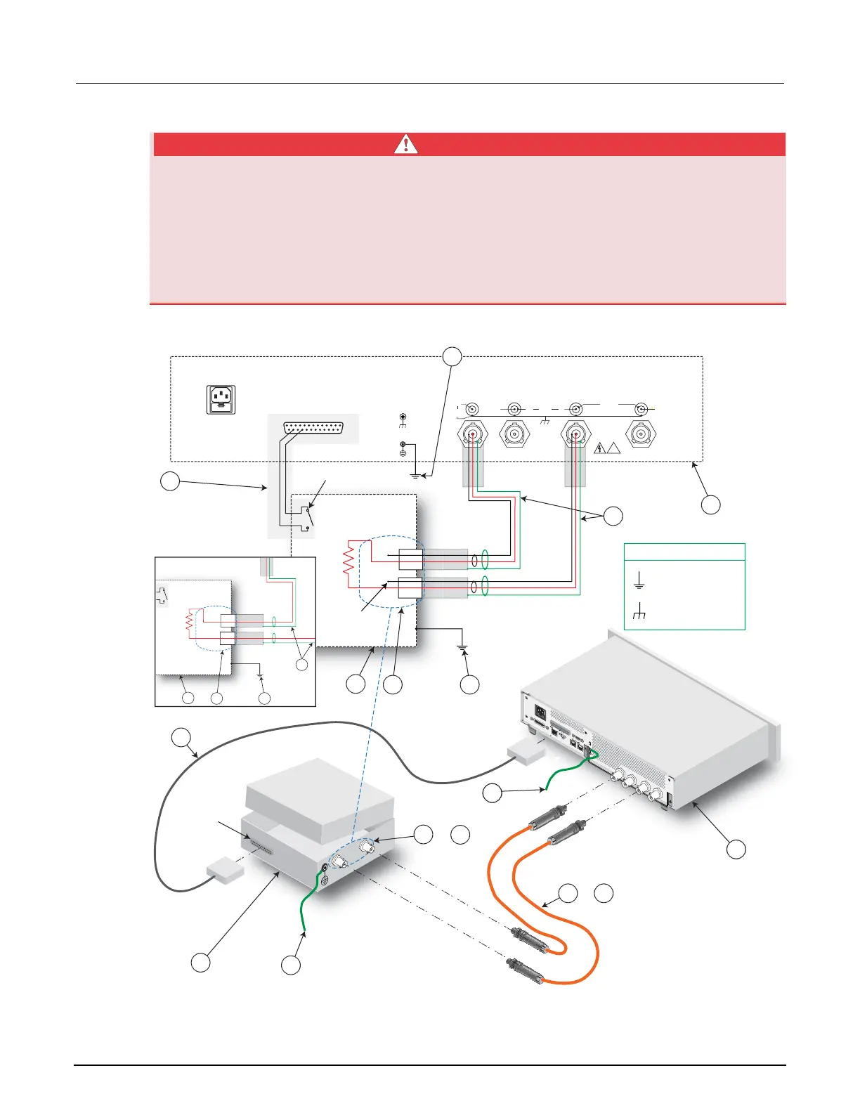
Connect the enclosure of all metal test fixtures to protective earth (safety ground). See your specific
test fixture for information. Nonconductive test fixtures must be rated to double the maximum
capability of the test equipment in the system.
Figure 13: Two-wire resistance connections
WARNING
LINE RA
TING
100-240
V
AC
50, 60 Hz
350
V
A
MAX.
LINE FUSE
SLOWBLOW
5.0
A, 250 V
NO INTERNAL OPERA
T
OR SERVICEABLE P
A
RTS,
SER
VICE B
Y
QUALIFIED PERSONNEL
ON
LY
.
REPLACE FUSE WITH SAME
TYPE AND R
A
TING.
WARNING:
INPUT/OUTPUT CURRENT: 120 mA MAX.
!
!
SENSE
LO
HI
LO
GUARD
SENSE
HI
LO
3030 VDC
MAX.
250 V
MAX.
DIGITAL I/O
HI LO
DIGITAL I/O
!
SENSE
LO
HI
LO
GUARD
SENSE
HI
LO
3030 VDC
MAX.
250 V
MAX.
Model 2657A
DIGITAL I/O
1
14
13
25
4 ***
1
7
4 ***
3
6
7
Guard**
LO
HI
DUT
3
1
2 *
2
* Interlock switch shown
in OFF / lid open
position
** See WARNING
*** Additional connections
for redundant protective
earth (safety ground)
may be required
6 or
5 or
9
8
5
Ground symbols
Chassis
Protective earth
(safety ground)
4 ***
LO
HI
DUT
3
8
9
SHV cables
Test fixture
interlock
switch
connection
+5 VDC