1-12
IV2 Series User's Manual (Control Panel)
Name and Function of Each Part
Name and Function of Each Part
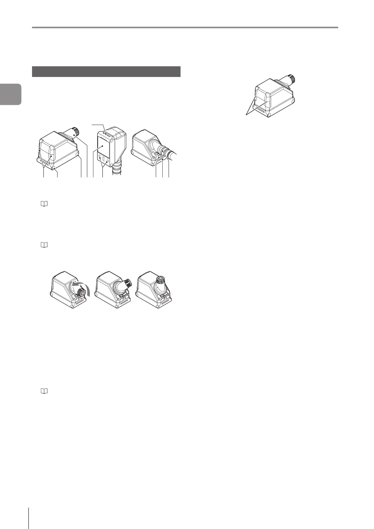
Sensor Head
IV2-G500CA
IV2-G500MA
IV2-G150MA
IV2-G300CA
IV2-G600MA
Name and function of each part of the
sensor head
1 2 2 3 4 5 6 78
8
1 Indicator light
Indicates the operating status of the sensor head.
“Operation of the sensor head indicator light” (Page
1-12)
2 Mounting holes
Used for mounting the sensor head.
Also used for mounting to the dome attachment for IV2
series.
“Mounting the sensor head” (Page 2-3)
3 Connector for sensor head/amplier cable for IV2
series
The connector can rotate.
Example of rotating
4 Camera and built-in light
5 Mounting location for the spread lens attachment
for IV2-G150MA
6 Mounting location for polarizing lter attachment
for IV2 series,
polarizing lter attachment for IV2-G300CA,
polarizing lter attachment for IV2-G600MA
7 Connector for sensor head/amplier cable for IV2
series
“Cables” (Page 2-11)
8 Dome attachment mounting location
Operation of the sensor head indicator light
Indicator light
Green (ON) ...... The total status result is “OK”.
Green (Blink) .... Under startup or setting in progress.
Operation stopped.
Blinks once a second.
Red (ON) .......... The total status result is “NG”.
Red (Blink) ....... An error occurred.
(OFF) ...............-Standbystatusuntiltherst
judgmentnishesafterstartingthe
operation or after switching the
program number.
- The versions of the sensor head and
sensoramplierdonotmatch.
- An incompatible sensor head is
connected.
Green and red
are blinking
alternately
... “LED Blinking” is requested.
Flash LED is requested from the
PROFINET communications I/O
controller.
1
Getting Started