2-14
IV2 Series User's Manual (Control Panel)
Cables
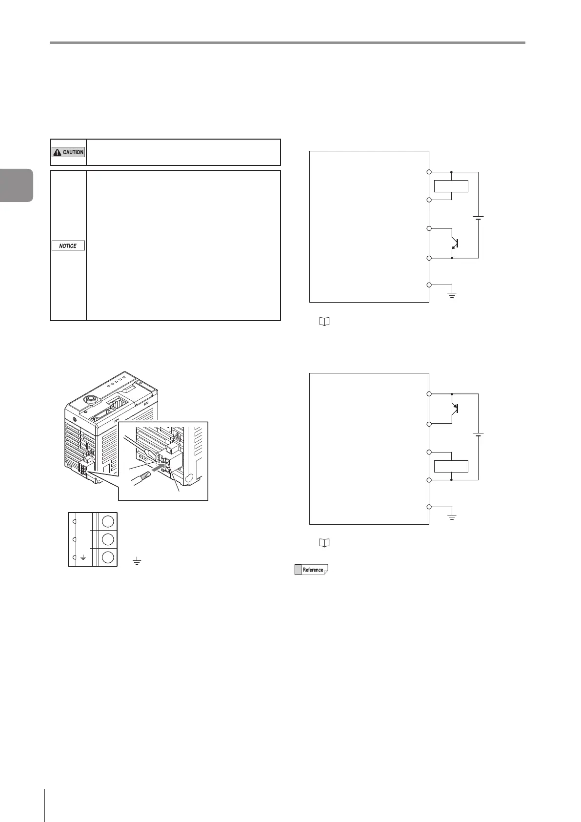
Supplying power to the sensor amplier
The power terminal block is mounted on the bottom of the
sensoramplier.
Use wire whose temperature rating is 80 ºC or
higher for the power supply.
Follow the instructions mentioned below to
avoid damage caused by bad connections.
The nominal cross-sectional area of the wire
for connecting the power should be 0.8 mm
2
to 1.3 mm
2
(AWG16 to 18).
Length of the insulation removed from the
wire should be around 9mm.
The stripped part of the wire should not be
soldered (pre-soldered).
Insert the wires to the power terminal block
completely.
Wire the power cables directly into the
terminal block.
Use a rod terminal when using a crimp-type
terminal.
1
Insert the wire to B by pushing A in with a
screwdriver.
Pullthewireoutslightlytoconrmthatitissecured.
B
A
0V
24V
24 V
Wire to DC 24 V of the power
supply.
0V Wire to 0 V of the power supply.
Ground.
Connection diagram
Selecting NPN output
When NPN is selected as the Polarity
DC24V
(NPN)
24 V line of power terminal
block (DC24V)
OUT1 to OUT8*
IN1 to IN8*
0 V line of power terminal block
(0 V)
FG of power terminal block
External deviceSensorAmplier
Load
* For the terminal number and wiring color, refer to
“●TerminalNumberandWiringColoroftheI/O
Cable for the IV2 Series (OP-87906)” (Page 2-13).
Selecting PNP output
When PNP is selected as the Polarity
DC24V
(PNP)
24 V line of power terminal
block (DC24V)
IN1 to IN8*
OUT1 to OUT8*
0 V line of power terminal block
(0 V)
FG of power terminal block
External deviceSensorAmplier
Load
* For the terminal number and wiring color, refer to
“●TerminalNumberandWiringColoroftheI/O
Cable for the IV2 Series (OP-87906)” (Page 2-13).
0 V and FG are insulated.
2
Installation and Connection