2-3
IV2 Series User's Manual (Control Panel)
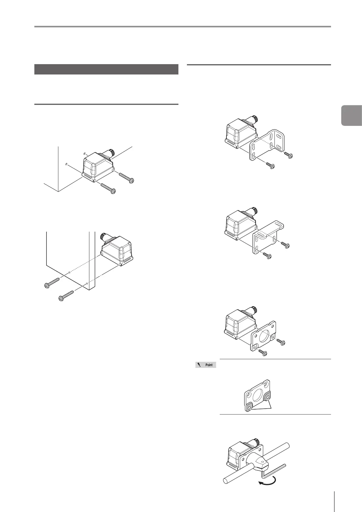
Mounting the Sensor
Mounting the sensor head
IV2-G500CA
IV2-G500MA
IV2-G150MA
IV2-G300CA
IV2-G600MA
Mounting the sensor head
When screws are secured from the sensor
head
Screw : M3 x 2
Tightening torque : 0.3 to 0.6 N·m
When screws are secured from the wall
Screw : M4 x 2
Tightening torque : 0.7 to 1.5 N·m
Screw hole on the sensor head: M4 female (whose
length of screw engagement should be 2.5 to 3.5 mm)
Attaching the optional mounting bracket
When using the vertical mounting bracket
for IV2 series (OP-87908)
Attach the bracket using the screws attached to OP-
87908.
Tightening torque : 0.7 to 1.5 N·m
Mounting
examples
When using the transverse mounting
bracket for IV2 series (OP-87909)
Attach the bracket using the screws attached to OP-
87909.
Tightening torque : 0.7 to 1.5 N·m
Mounting
examples
When using the adjustable bracket for IV2
series (OP-87910)
1
Attach the bracket using the screws attached to
OP-87910.
Tightening torque : 0.7 to 1.5 N·m
Mounting
examples
When using the adjustable bracket for IV2
series (OP-87910), connect the convex part to
the sensor head.
Convex part
2
Mount the bracket on the support side to x.
Tightening torque : 5 N·m
Mounting
examples
2
Installation and Connection
 Loading...