2-13
IV2 Series User's Manual (Control Panel)
Cables
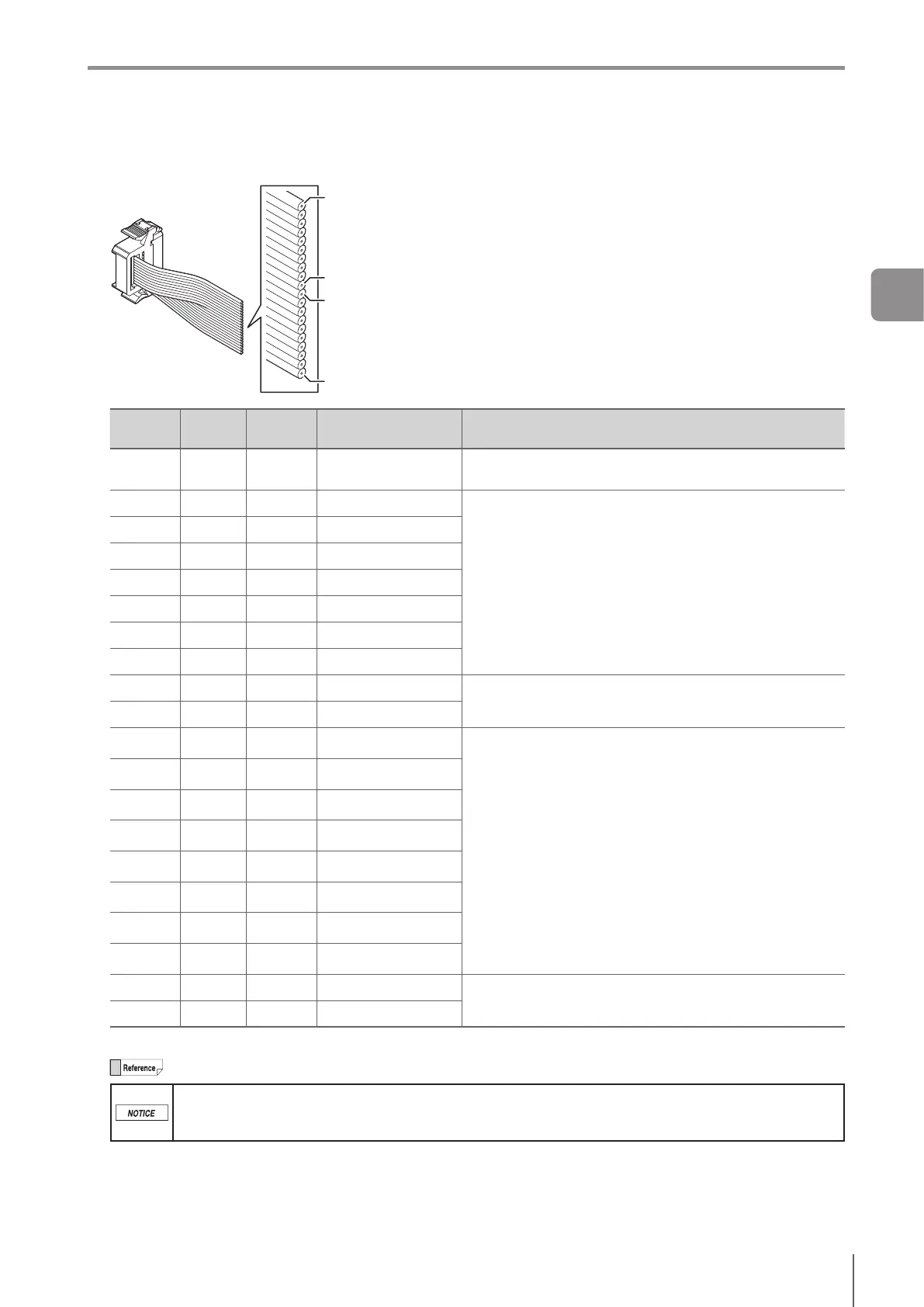
Terminal Number and Wiring Color of the I/O Cable for the IV2 Series (OP-87906)
A1 (brown)
A10 (black)
B1 (brown)
B10 (black)
Terminal
No.
Wiring
color
Name
Assigning default
value
Description
A1 Brown IN1 Ext.Trigger↑
Set external trigger.
Risingtiming(↑)orfallingtiming(↓)canbeset.
A2 Red IN2 OFF
Input assignable function
Program bit0 to bit6
Clear Error
Ext. Master Save
Stop saving the SD card
OFF (not used)
A3 Orange IN3 OFF
A4 Yellow IN4 OFF
A5 Green IN5 OFF
A6 Blue IN6 OFF
A7 Purple IN7 OFF
A8 Gray IN8 OFF
A9 White
Unused
Unused
Unused
A10 Black
Unused
Unused
B1 Brown
OUT1
Total Status (N.O.)
Output assignable function
Total Status
Tot.StatusNG
RUN
BUSY
Ready
Strobe
Error
SD card error
Pos. Adj.
Status result of each tool (Tool 1 to 16)
Logical operation result of each tool (Logic 1 to 4)
OFF (not used)
B2 Red
OUT2
BUSY (N.O.)
B3
Orange
OUT3
Error (N.C.)
B4 Yellow
OUT4
OFF
B5 Green
OUT5
OFF
B6 Blue
OUT6
OFF
B7 Purple
OUT7
OFF
B8 Gray
OUT8
OFF
B9 White
Unused
Unused
Unused
B10
Black
Unused
Unused
Cablespecication:AWG28
The output assignment, N.O./N.C., and input line assignment can be changed.
Individually insulate the unused input-output cables.
For input cables of this sensor, connect with non-contact output (transistor output/SSR output). For
contact output (relay output), incorrect input may occur due to contact bouncing.
2
Installation and Connection
 Loading...