3-26 Keysight E5260/E5270 User’s Guide, Edition 6
Installation
Mounting Connectors
To Make an Interlock Circuit
The interlock circuit is designed to prevent electrical shock when a user touches the
measurement terminals.
CAUTION You must install an interlock circuit on a shielding box to prevent hazardous
voltages when the door of the shielding box is open.
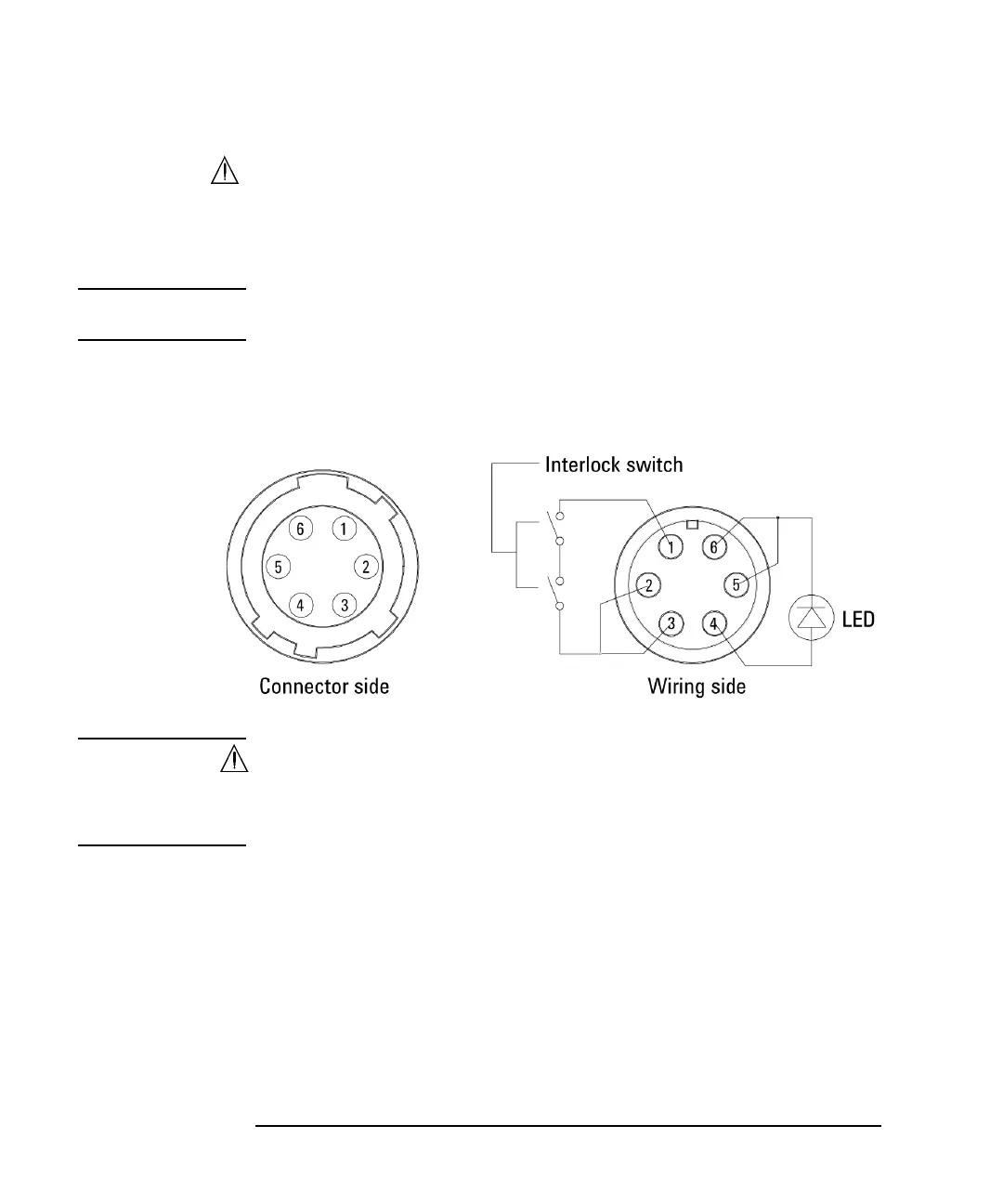
Figure 3-8 shows the pin assignments of the interlock connector that should be
mounted on a connector plate or test fixture.
Figure 3-8 Interlock Connector Pin Assignments
WARNING Dangerous voltage, instrument maximum output voltage may appear at Force,
Guard, and Sense terminals if the Interlock terminal is closed.
Une tension dangereuse, une tension de sortie maximale de l'appareil peut
apparaître aux bornes Force, Guard et Sense si la borne Interlock est fermée.