DIAGNOSTICS Checkout Procedures
10DEC05
DG4825-1
Page
128 of 180
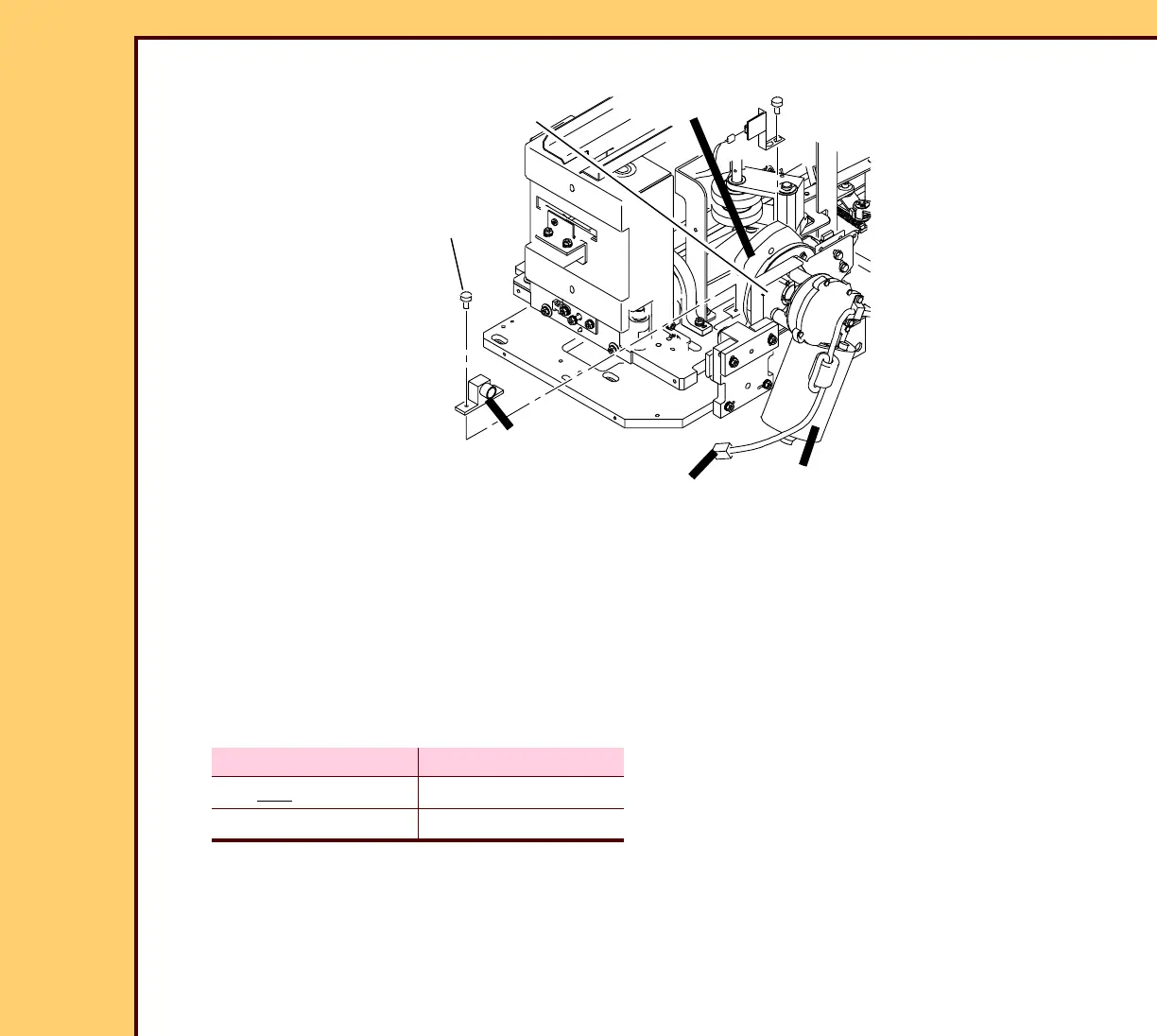
CAM MOTOR M1
1 Remove:
• 2 SCREWS
• SLED CAM FOLLOWER
2 Manually move the SLED and check for binds.
3 Check the DUPLEX CAM for binds.
4 Check for 24 V DC at the CONNECTOR of the CAM MOTOR M1:
5 Check for broken wires to the CAM MOTOR M1.
6 Do the checkout procedure for the MOTION SYSTEM CONTROL BOARD A1.
DUPLEX CAM Voltage
Not moving 0 V DC
Moving 24 V DC
H194_1000AC
H194_1000ACC
2 SCREWS
SLED
CAM MOTOR M1
DUPLEX CAM
CONNECTOR
FOLLOWER
SLED CAM
 Loading...


