DIAGNOSTICS Checkout Procedures
10DEC05
DG4825-1
Page
143 of 180
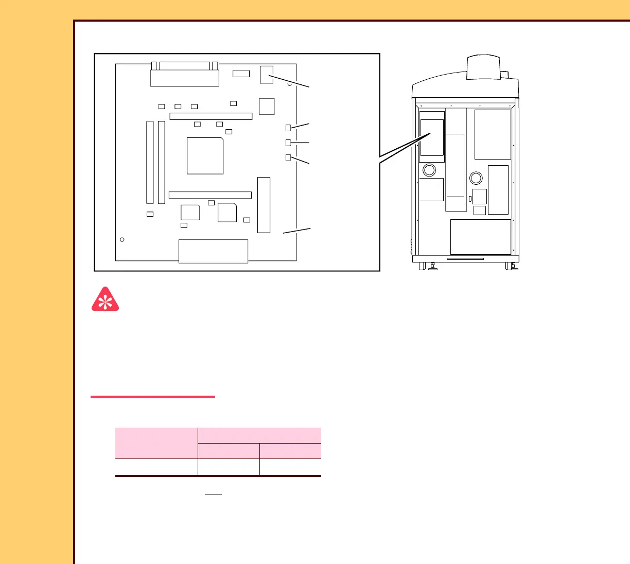
DIGITIZER BOARD A3
Important
The DIGITIZER BOARD A3:
• receives the image data from the PMT/DAS BOARD A5
• changes the input 24 V DC to 5 V DC
• sends the timing signal to the GALVO BOARD A4
1 Check for correct voltages on CONNECTOR P2:
2 If the voltage is not
correct, do the checkout procedure POWER SUPPLY PS1.
Voltage
MULTIMETER
Ground Positive
+24 V DC P2-2 P2-1
H194_0035BC
BOARD A3
DIGITIZER
TP3
TP2
TP1
P2
CONNECTOR
H194_0035BCA
 Loading...


