5.10.5 Homing Mode Sequence
The homing movement is started by setting Bit 4 (positive edge). The successful conclusion is
indicated by Bit 12 in the status word (see Object 6041h). Bit 13 indicates that an error occurred
during the homing movement. In this case, the error code must be evaluated (error register:
Objects 1001h, 1003h, manufacturer status: Object1002h).
Bit 4 Meaning
0 homing inactive
0 → 1 start homing movement
1 homing active
1 → 0 interruption of homing movement
Bit 13 Bit 12 Meaning
0 0 reference point not set, or homing movement not yet finished
0 1 reference point set, homing movement finished
1 0 homing movement could not be successfully concluded (lag error)
1 1 impermissible state
5.11 Profile Position Mode (pp)
5.11.1 General Information
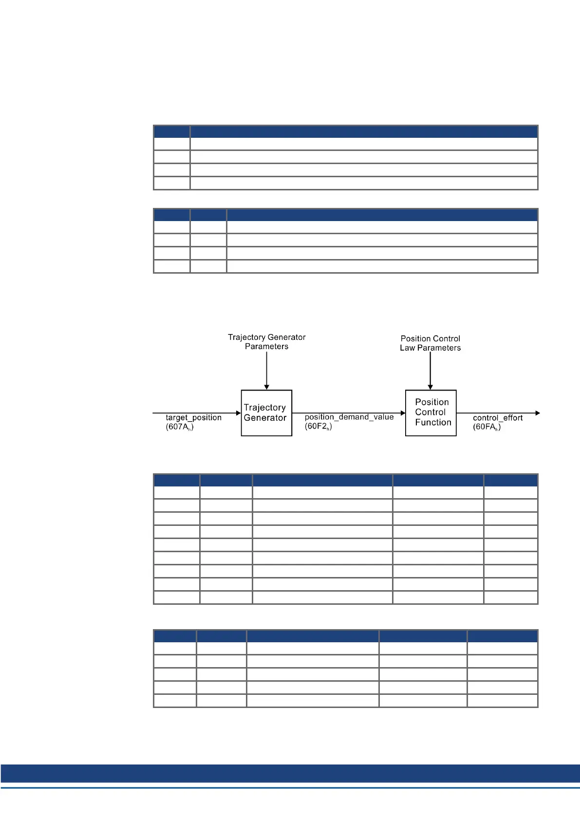
The overall structure for this mode is shown in this figure:
The special handshake procedure for the control word and status word see (➜ # 90).
5.11.2 Objects that are defined in this section
Index Object Name Type Access
607Ah VAR target position INTEGER32 rw
607Dh ARRAY software position limit INTEGER32 rw
607Fh VAR max. profile velocity UNSIGNED32 rw
6080h VAR max. motor speed UNSIGNED32 rw
6081h VAR profile velocity UNSIGNED32 rw
6083h VAR profile acceleration UNSIGNED32 rw
6084h VAR profile deceleration UNSIGNED32 rw
6085h VAR quick stop deceleration UNSIGNED32 rw
6086h VAR motion profile type INTEGER16 rw
5.11.3 Objects that are defined in other sections
Index Object Name Type Section
6040h VAR control word INTEGER16 dc (➜ # 58)
6041h VAR status word UNSIGNED16 dc (➜ # 60)
6093h ARRAY position factor UNSIGNED32 fg (➜ # 67)
6094h ARRAY velocity encoder factor UNSIGNED32 fg (➜ # 68)
6097h ARRAY acceleration factor UNSIGNED32 fg (➜ # 71)
S300-S700 CANopen | 5 CANopen Drive Profile
Kollmorgen | kdn.kollmorgen.com | December 2019 85

 Loading...


