S300-S700 CANopen | 6 Appendix
6.3.9 Example: Using the Profile Position Mode
This example shows the operation of the Profile position mode. For this, the PDOs are set as fol-
lows:
First RPDO
No special mapping necessary, because the default mapping enters the controlword RXPDO1.
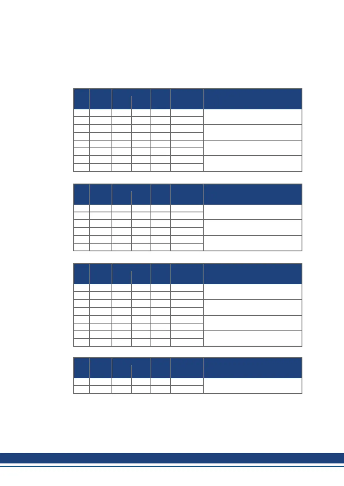
Second RPDO
COB-
ID
Control
byte
Index
Sub-
index
Data Comment
Low
byte
High
byte
603 2F 01 16 00h 00 00 00 00
RPDO2: delete mapping
583 60 01 16 00h 00 00 00 00
603 23 01 16 01h 20 00 7A 60
RPDO2, entry 1: target_position
583 60 01 16 01h 00 00 00 00
603 23 01 16 02h 20 00 81 60
RPDO2, entry 2: profile_velocity
583 60 01 16 02h 00 00 00 00
603 2F 01 16 00h 02 00 00 00
enter number of mapped objects
583 60 01 16 00h 00 00 00 00
First TPDO
COB-
ID
Control
byte
Index
Sub-
index
Data Comment
Low
byte
High
byte
603 2F 00 1A 00h 00 00 00 00
TPDO1: delete mapping
583 60 00 1A 00h 00 00 00 00
603 23 00 1A 01h 10 00 41 60
TPDO1, entry 1: profile statusword
583 60 00 1A 01h 00 00 00 00
603 2F 00 1A 00h 01 00 00 00
enter number of mapped objects
583 60 00 1A 00h 00 00 00 00
Second TPDO
COB-
ID
Control
byte
Index
Sub-
index
Data Comment
Low
byte
High
byte
603 2F 01 1A 00h 00 00 00 00
TPDO2: delete mapping
583 60 01 1A 00h 00 00 00 00
603 23 01 1A 01h 20 00 64 60
TPDO2, entry 1: position_actual_value
583 60 01 1A 01h 00 00 00 00
603 23 01 1A 02h 20 00 6C 60
TPDO2, entry 2: velocity_actual_value
583 60 01 1A 02h 00 00 00 00
603 2F 01 1A 00h 02 00 00 00
enter number of mapped objects
583 60 01 1A 00h 00 00 00 00
The second TPDO should be sent with every SYNC by the servoamplifier.
COB-
ID
Control
byte
Index
Sub-
index
Data Comment
Low
byte
High
byte
603 2F 01 18 02h 01 00 00 00
TPDO2 with every SYNC
583 60 01 18 02h 00 00 00 00
124 Kollmorgen | kdn.kollmorgen.com | December 2019

 Loading...


