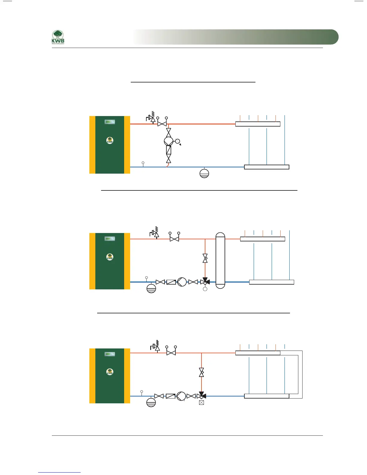
18.2 Hydraulic diagrams
Return flow boost, hydr. circuit boiler circuit MBEH0001_e
M
M
RF
RF
Variant 1: Return flow boost with bypass pump
Variant 2: Return flow boost with motor mixing valve (or thermal valve)
Hydr. shunt or buffer
USP, USV
USP, USV, SHV, TDS (TDS only with motor mixing valve)
USP: Min. 55°
USV, SHV, TDS: Min. 55°
– Only for distributors under pressure (no short-circuit!)
– No buffer, hydraulic shunt is not possible!
– Bypass pump is speed-regulated (output, see terminal diagram)
– Use for installation of a buffer or a hydraulic shunt
– No distributor short circuit
– Either thermal valve or motor mixer (mixer output, see terminal diagram)
Variant 3: Return flow boost with thermal mixing valve (or motor mixing valve)
– Without buffer or hydr. shunt the distributor must be de-pressurized (short circuit!)
– Short circuit: DN should equal DNv, however minimum DNk! Pressure loss < 5 mbar
– Either thermal valve or motor mixer (mixer output, see terminal diagram)
RS
Short circuit
USP, USV , SHV
Valve core 55 °C°
DN
DNv
DNv
DNk
DNk
(Pressure loss must be less than 5 mbar)
These illustrations are principle representations. The hydr. configuration/detail planning must be executed by
the installer. Suitable return flow boost armatures are available from KWB.
MA-Easyfire 10.2008_EN.indd 163MA-Easyfire 10.2008_EN.indd 163 30.03.2009 13:32:06 Uhr30.03.2009 13:32:06 Uhr
 Loading...