2 System installation
2.1.11.2 Mains supply
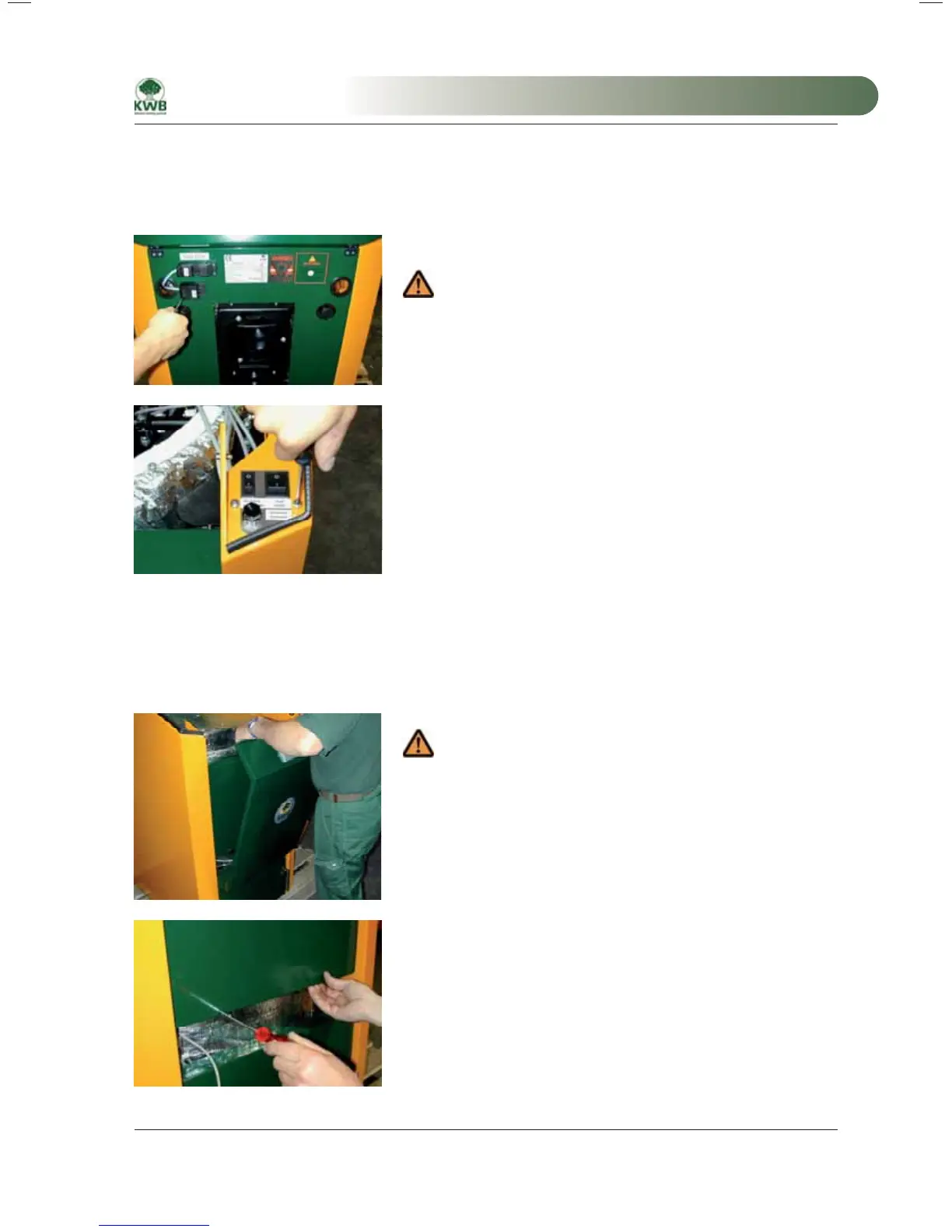
The system’s mains supply is executed via a 3-pole Wieland plug-in connector (labelled “Power”) on the rear wall
of the boiler.
Open the provided coupling and connect the power supply.
Ensure that the polarity is correct!
Mains supply
From this point the power supply is routed via the main switch 1 to the
boiler I/O module of the system.
Main switch
2.1.11.3 Junction box
All connection points for the electrical installation are provided in the junction box that is arranged below the boiler
cladding. Proceed as follows to obtain access to the junction box:
Lift the front cladding out of the holder and put it down to the side.
To avoid damage to front cladding if it should fall, position the front
cladding with the outside facing the side wall. After opening the
control unit cover, you can unplug the connecting cable and put the
front cladding down to the side.
Front cladding
Loosen the two screws of the control unit cover and remove them.
Cover, junction box
MA-Easyfire 10.2008_EN.indd 31MA-Easyfire 10.2008_EN.indd 31 30.03.2009 13:30:00 Uhr30.03.2009 13:30:00 Uhr
 Loading...