12 Pellet Stirrer Plus
12.5 Installing the elbow worm
See point 10.5.
12.6 Installing the head piece with drop shaft
See point 10.6.
12.7 FE connection on the burner
See point 10.7.
12.8 Installing the Stirrer Plus
Combined FE components: Ascending worm, suction head, drop shaft
1.) Install the trough supports.
Install the trough supports on the connecting trough or suction head.
For suction head and drop shaft also install the trough supports on the
motor side.
Place the completely assembled parts as shown in the plans. For
ascending worm systems ensure proper connection to the boiler
(connecting hose should be installed vertically if possible).
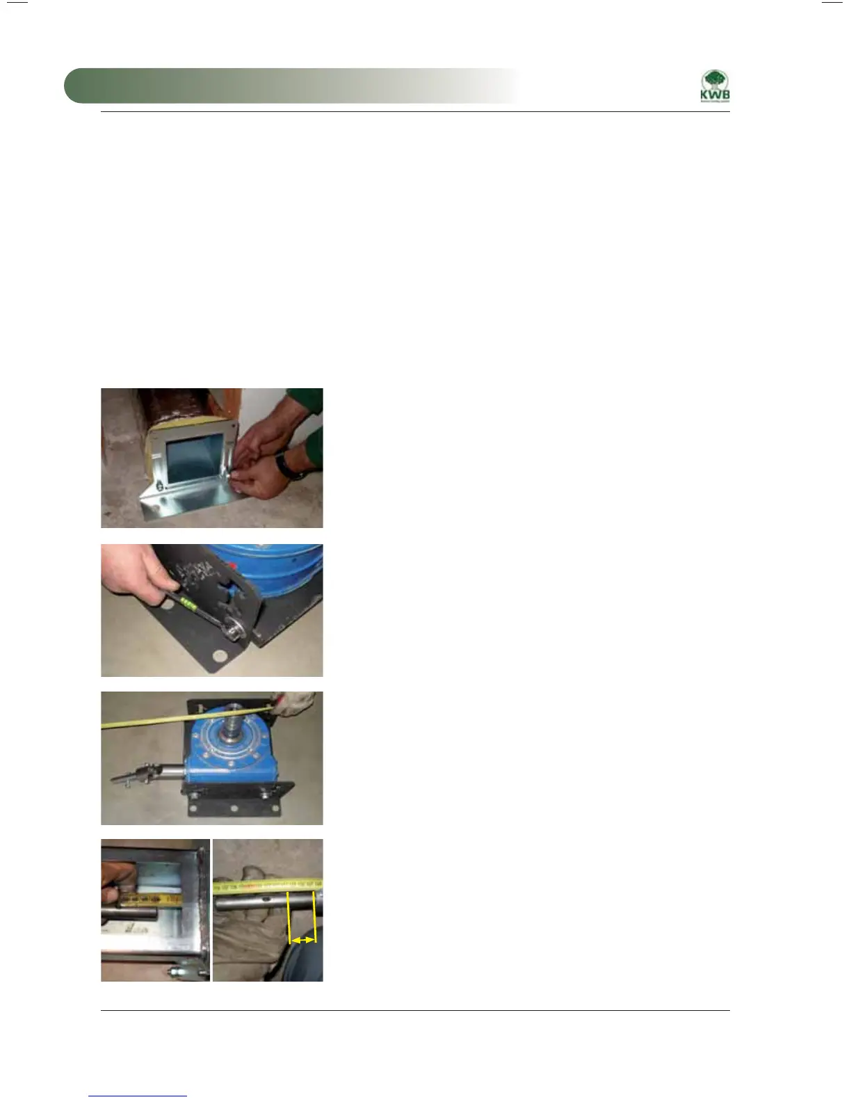
2.) Adjust the support angle of the gear unit bracket
Adjust the height of the gear unit using the two gear unit support
brackets. The trough centre should be at the same horizontal height as
the middle of the drive shaft.
It is possible to adjust the gear unit support brackets in 20 mm
increments. Use the support brackets to make fine adjustments to the
troughs.
3.) Place the gear unit
Place the gear unit at the mid point of the storage room as shown and
turn it in such a manner that the shaft joint points in the direction of the
worm trough, with no offset angle if possible.
20
4.) Measure the length of the conveyor worm
Measure the distance from the bore of the last conveyor worm to
the beginning of the shaft joint on the gear unit. From this dimension
subtract 20 mm (used for fine adjustment of the shaft joint).
MA-Easyfire 10.2008_EN.indd 120MA-Easyfire 10.2008_EN.indd 120 30.03.2009 13:31:06 Uhr30.03.2009 13:31:06 Uhr
 Loading...