4 Operation, specialist
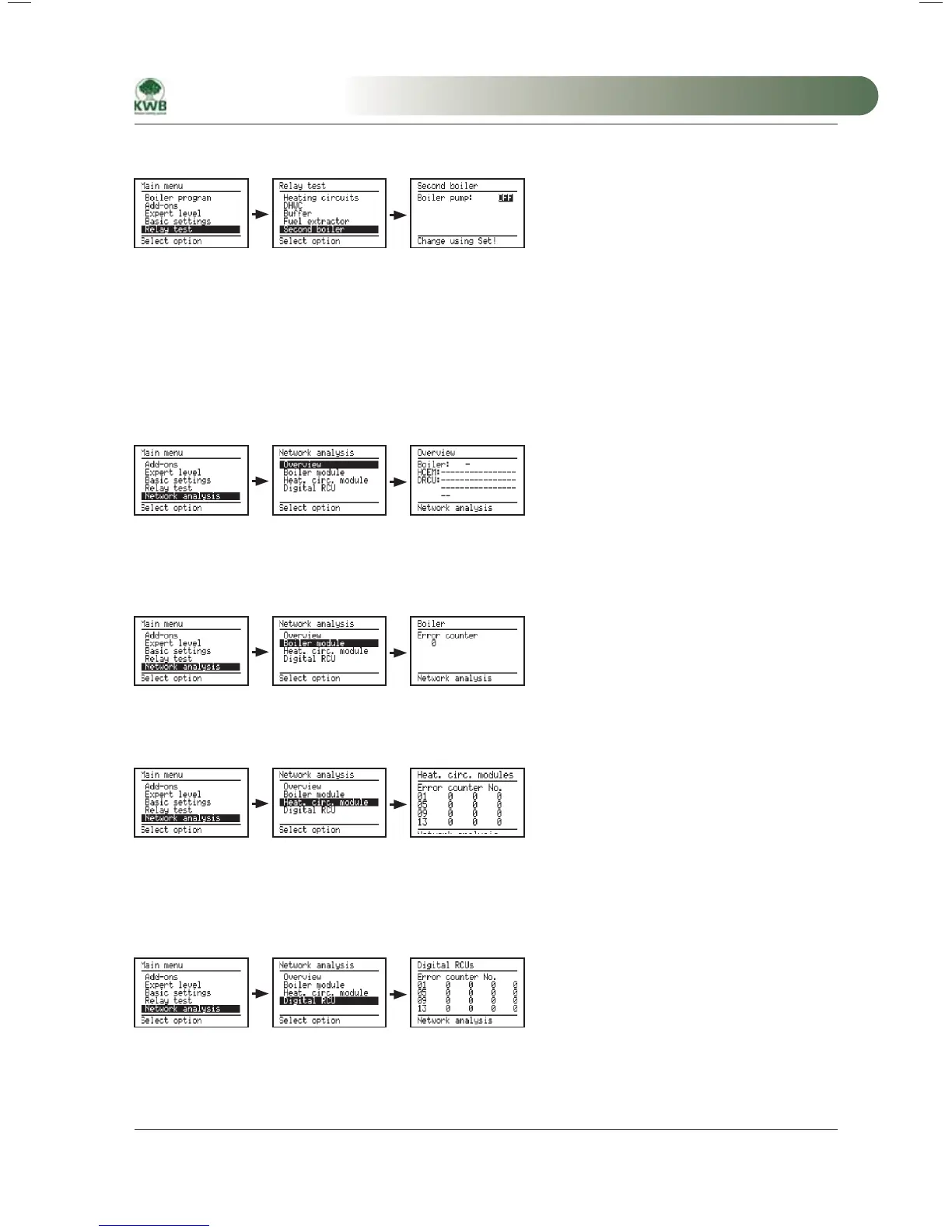
4.3.6 Second boiler
Boiler pump SB: Boiler pump of the second boiler
4.4 Menu item – Network Analysis
The network analysis function is used to analyze problems of individual bus stations. The counters are reset to 0
each time there is a power failure. Additional analyses are possible with the alarm log and the alarm statistics.
4.4.1 Overview
In this screen all possible bus nodes are presented in order to analyze failures. A “–” indicates that communication
with the network station is functioning. If this is not the case the last digit of the failed node is displayed.
4.4.2 Boiler module
The error counter shows the number of communication errors with the boiler I/O module.
4.4.3 Heating circuit module
The error counter shows the number of communication errors with the heating circuit expansion modules. In
columns two to five the errors are displayed for four devices, starting with the device that has its station number
in the first column.
4.4.4 Dig. remote control unit
The error counter shows the number of communication errors with the digital remote control units. In columns
two to five the errors are displayed for four devices, starting with the device that has its station number in the first
column.
MA-Easyfire 10.2008_EN.indd 59MA-Easyfire 10.2008_EN.indd 59 30.03.2009 13:30:09 Uhr30.03.2009 13:30:09 Uhr
 Loading...