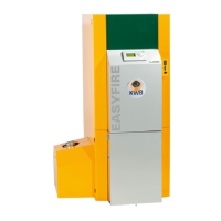
BCU
Control option
2 DRCU
Control option
1 DRCU, 1 ARCU
Control option
2 ARCUs
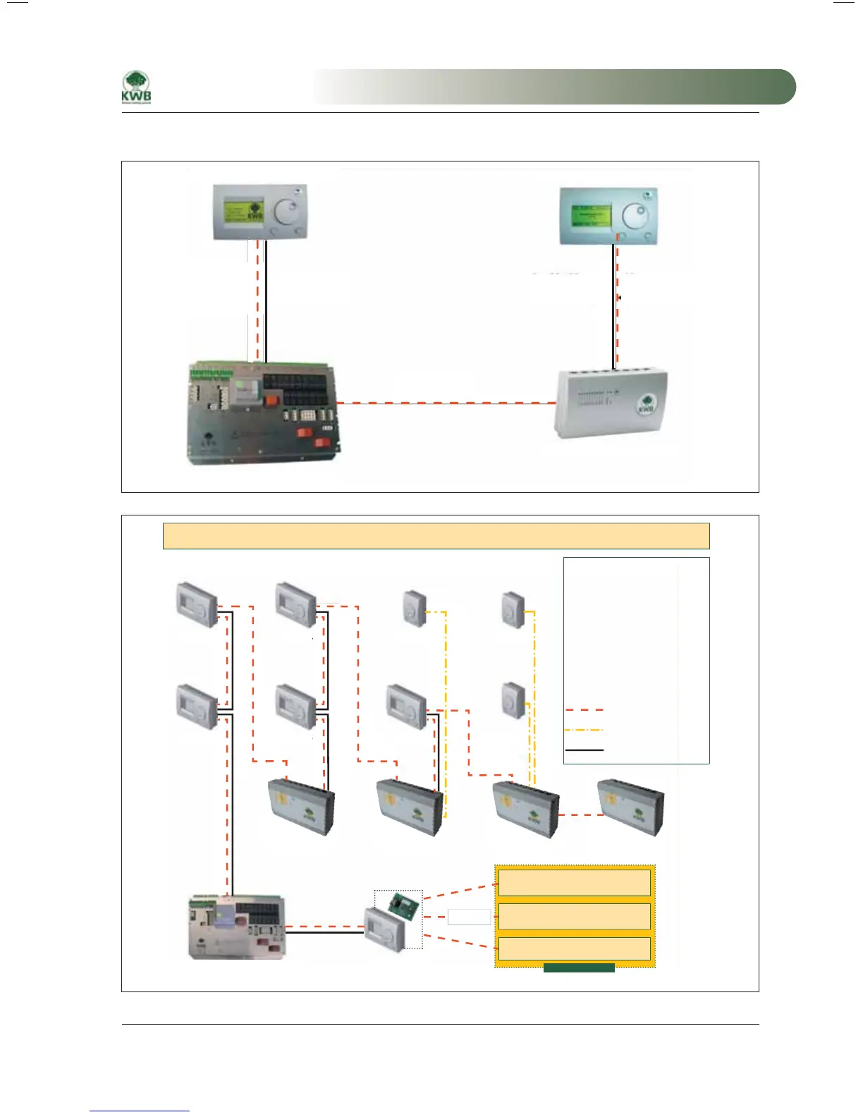
HCM 4 to 16
BOILER I/O module (GM)
Cabling diagram for networks for the KWB Comfort control unit Dated: December 2007
HCM 1 HCM 3
HCM 4 to 18
HCM 1
Legend:
BCU Boiler control unit
DRCU Digital remote control unit
ARCU Analogue remote control unit
HCM
Heating circuit
expansion module
BM Base module (I/O board)
NWC Network card
Bus RS 485 2-pole
Analogue line for sensor
Data line
with 24 V DC supply
Open interface
EXTENSIONS
NWC
VISIO
Modem
SMS module
GSM module – antenna
NWC
DRCU 2
DRCU 1
DRCU 4
DRCU 3
ARCU
DRCU 5
ARCU 3
ARCU 2
etc.
Cabling, network
Bus RS 485
2-pole A+B
Boiler control unit
Digital remote control unit
Boiler I/O module
Heating circuit expansion module
MA-Easyfire 10.2008_EN.indd 33MA-Easyfire 10.2008_EN.indd 33 30.03.2009 13:30:02 Uhr30.03.2009 13:30:02 Uhr
 Loading...