Maintenance and Service
Laborie NXT Pro Owner’s Manual LBL-00146, MAN2010 92
5.3.2.1 Verifying EMG Capability
To begin verifying calibration for Roam NXT EMG capability, gather one calibrated signal
generator (capable of generating sinusoidal waves at 10 Hz, 200 µV) with one alligator
cable, three touchproof 1.5 mm connectors, and one EMG input cable. To complete
calibration verification:
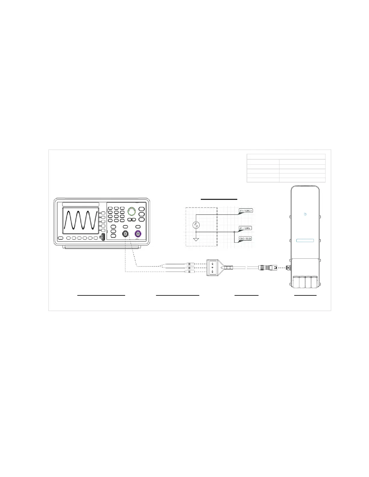
1. Set up a signal generator; prepare to create a sine wave with 10 Hz, and 200 µV.
2. Connect the touchproof connectors to the signal generator using the alligator cable.
3. Connect the EMG input cable to the connection point located on the PIM NXT.
4. Insert touchproof connectors into the EMG input cable. Refer to Figure 76 for a
graphic representation of the signal generator and the Roam NXT setup.
Figure 76: Wiring Diagram—EMG Calibration Verification with a Waveform Generator
5. After the signal generator and the Roam NXT are connected as displayed in Figure
76, begin generation of a sine wave with 10 Hz and 200 µV.
6. From the Patients section, select a patient file created for verification purposes, and
then, on the UDS tab, choose the Urology Urodynamics test and click the Start
Study button; the Preview phase will begin.
7. Verify that the graph in the preview phase shows EMG as a 200 µ sine wave.
 Loading...