Maintenance and Service
Laborie NXT Pro Owner’s Manual LBL-00146, MAN2010 95
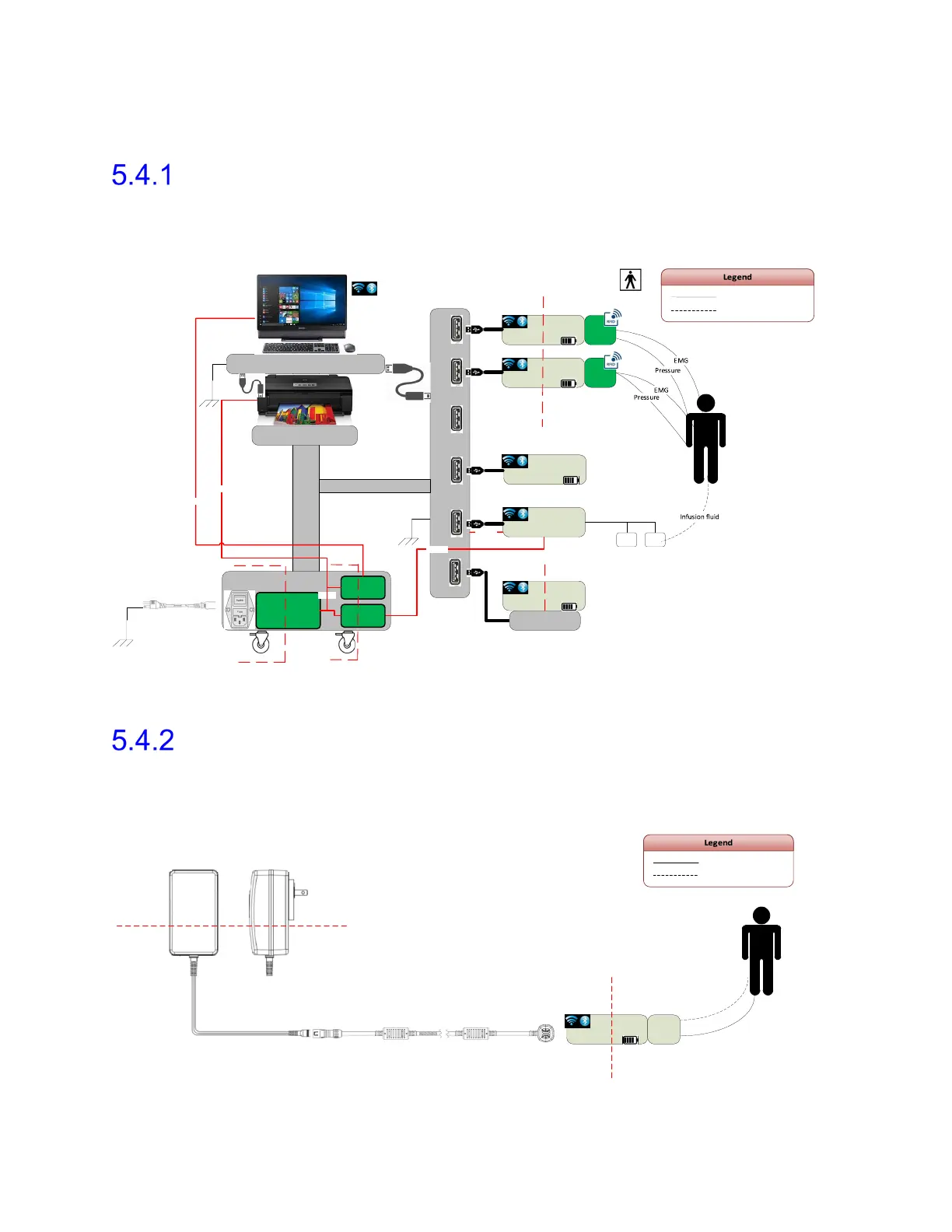
5.4 Configuration
NXT PRO Electrical Isolation Diagram
Refer to the diagram shown in Figure 79 for a visual representation of the NXT Pro electrical
isolation from main supply. For further information regarding electrical isolation, contact
Laborie Service.
HUB
Spine
Spine
Work Station
BASE
AC/DC
18V~2 4V
PIM1
PIM2
18V~2 4V
Roam Base 1
Roam Base 2
Pump
18V
Isolation Barrier2
Isolation Barrier1
100-240VAC
50/60Hz
Direct electrical contact
Indirect electrical contact
Docking Station
UroCap 6
Extens ion
cable
UPP Puller NXT
Figure 79: NXT Pro Isolation Diagram
Roam NXT and Wall Charger Isolation Diagram
Refer to the diagram shown in Figure 80 for a visual representation of the method to isolate
the Roam NXT from main supply main when configured with a wall charger. For further
information regarding electrical isolation, contact Laborie Service.
Roam
Direct electrical contact
Indirect electrical contact
100-240VAC
50/60Hz
Isolation Barrier1
NXT Module Power
Supply
P/N:POW1033
Cable NXT POGO Pin to
BINDER 3 meter
P/N:CAB1081
Isolation Barrier2
PIM
EMG
Press ure
Figure 80: Roam NXT and Wall Charger Isolation Diagram
 Loading...