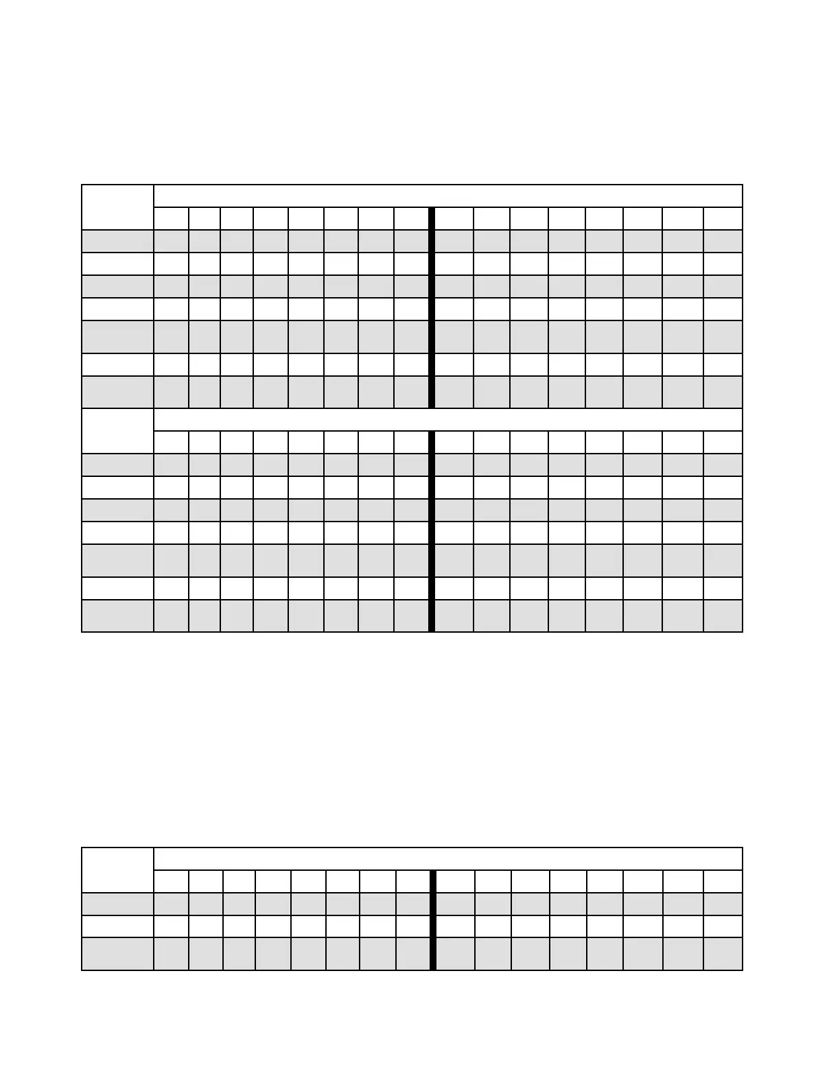
With two processors
The following table shows the sequence of populating memory modules (with the same capacity) for
independent mode when two processors (Processor 1 and Processor 2) are installed.
Table 29. Independent mode with two processors (DIMMs with same capacity)
Configura-
tion
DIMM slots
1 2 3 4 5 6 7 8 9 10 11 12 13 14 15 16
2 DIMMs 3
4 DIMMs 3 7
8 DIMMs
1
3 7 10 14
12 DIMMs 1 3 7 10 14 16
16 DIMMs
1,
2
1 3 5 7 10 12 14 16
24 DIMMs 1 2 3 4 7 8 9 10 13 14 15 16
32 DIMMs
1,
2
1 2 3 4 5 6 7 8 9 10 11 12 13 14 15 16
Configura-
tion
DIMM slots
17
18 19 20 21 22 23 24 25 26 27 28 29 30 31 32
2 DIMMs 19
4 DIMMs 19 23
8 DIMMs
1
19 23 26 30
12 DIMMs 17 19 23 26 30 32
16 DIMMs
1,
2
17 19 21 23 26 28 30 32
24 DIMMs 17 18 19 20 23 24 25 26 29 30 31 32
32 DIMMs
1,
2
17 18 19 20 21 22 23 24 25 26 27 28 29 30 31 32
Notes:
1. DIMM configurations that support the Sub NUMA Clustering (SNC) feature, which can be enabled via
UEFI. SNC is not supported if DIMM population does not follow the sequence indicated by the table
above.
2. DIMM configurations that support Software Guard Extensions (SGX). See “Enable Software Guard
Extensions (SGX)” in Setup Guide to enable this feature.
The following table shows the sequence of populating memory modules (with the different capacities) for
independent mode when two processors (Processor 1 and Processor 2) are installed.
Table 30. Independent mode with two processors (DIMMs with different capacities)
Configura-
tion
DIMM slots
1 2 3 4 5 6 7 8 9 10 11 12 13 14 15 16
4 DIMMs 3 5
8 DIMMs 3 5 12 14
16 DIMMs
1,
2
1 3 5 7 10 12 14 16
256 ThinkSystem SR650 V2Maintenance Manual

 Loading...


