Mirroring mode
Memory-mirroring mode provides full memory redundancy while reducing the total system memory capacity
in half. Memory channels are grouped in pairs with each channel receiving the same data. If a failure occurs,
the memory controller switches from the DIMMs on the primary channel to the DIMMs on the backup
channel. The DIMM installation order for memory mirroring varies based on the number of processors and
DIMMs installed in the server.
In mirroring mode, each memory module in a pair must be identical in size and architecture. The channels are
grouped in pairs with each channel receiving the same data. One channel is used as a backup of the other,
which provides redundancy.
Follow the rules below when installing memory modules in mirroring mode:
• All memory modules to be installed must be of the same type with the same capacity, frequency, voltage,
and ranks.
• Mirroring can be configured across channels in the same iMC, and the total DDR4 memory size of the
primary and secondary channels must be the same.
With one processor
The following table shows the memory module population sequence for mirroring mode when only one
processor (Processor 1) is installed.
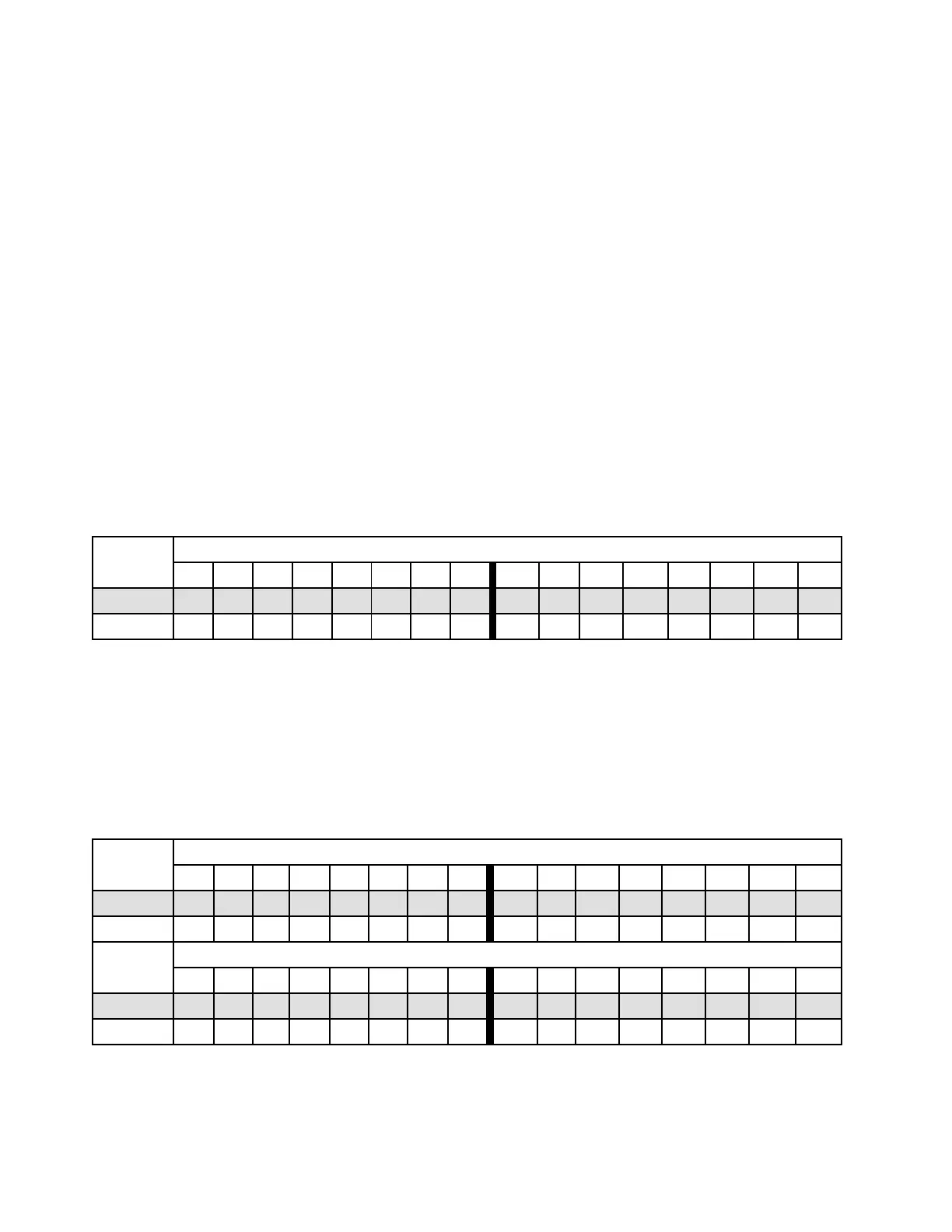
Table 31. Mirroring mode with one processor
Configura-
tion
DIMM slots
1 2 3 4 5 6 7 8 9 10 11 12 13 14 15 16
8 DIMMs 1 3 5 7 10 12 14 16
16 DIMMs 1 2 3 4 5 6 7 8 9 10 11 12 13 14 15 16
Note: DIMM configurations listed in the table support the Sub NUMA Clustering (SNC) feature, which can be
enabled via UEFI. SNC is not supported if DIMM population does not follow the sequence indicated by the
table above.
With two processors
The following table shows the memory module population sequence for mirroring mode when two
processors (Processor 1 and Processor 2) are installed.
Table 32. Mirroring mode with two processors
Configura-
tion
DIMM slots
1 2 3 4 5 6 7 8 9 10 11 12 13 14 15 16
16 DIMMs 1 3 5 7 10 12 14 16
32 DIMMs 1 2 3 4 5 6 7 8 9 10 11 12 13 14 15 16
Configura-
tion
DIMM slots
17 18 19 20 21 22 23 24 25 26 27 28 29 30 31 32
16 DIMMs 17 19 21 23 26 28 30 32
32 DIMMs 17 18 19 20 21 22 23 24 25 26 27 28 29 30 31 32
Note: DIMM configurations listed in the table support the Sub NUMA Clustering (SNC) feature, which can be
enabled via UEFI. SNC is not supported if DIMM population does not follow the sequence indicated by the
table above.
258 ThinkSystem SR650 V2Maintenance Manual

 Loading...


