Rear components overview
Drive LEDs
Each hot-swap drive comes with an activity LED and status LED and the signals are controlled by the
backplanes. Different colors and speeds indicate different activities or status of the drive. The following
illustration shows the LEDs on a Hard disk drive or solid–state drive.
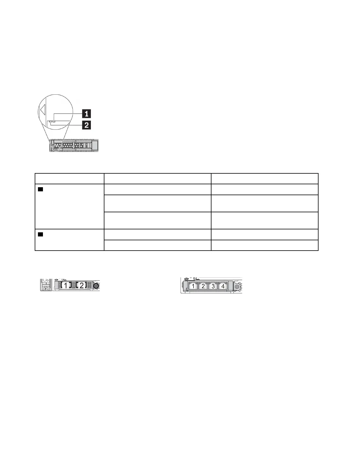
Figure 7. Drive LEDs
Drive LED
Status
Description
1 Drive status LED (right) Solid yellow
The drive has an error.
Blinking yellow (blinking slowly, about one
flash per second)
The drive is being rebuilt.
Blinking yellow (blinking rapidly, about four
flashes per second)
The RAID adapter is locating the drive.
2 Drive activity LED (left) Solid green
The drive is powered but not active.
Blinking green The drive is active.
Ethernet connectors
Figure 8. OCP 3.0 Ethernet adapter (two connectors, seen
from the rear)
Figure 9. Ports on the OCP 3.0 Ethernet adapter (four
connectors, seen from the rear)
The OCP 3.0 Ethernet adapter provides two or four extra Ethernet connectors for network connections.
By default, Ethernet connector 1 (the first port starting from the left in the rear server view) on the OCP 3.0
Ethernet adapter can also function as a management connector using the shared management capacity. If
the shared management connector fails, traffic can automatically switch over to another connector on the
adapter.
Hot-swap drives and drive bays
The drive bays on the front and rear of your server are designed for hot-swap drives. The number of the
installed drives in your server varies by model. When you install drives, follow the order of the drive bay
numbers.
The EMI integrity and cooling of the server are protected by having all drive bays occupied. Vacant drive
bays must be occupied by drive fillers.
50
ThinkSystem SR650 V2Maintenance Manual

 Loading...


