Installation
8200SHB01994-32
- Themotorcableshouldbeasshortaspossiblebecauseofthepositive
effect on the drive characteristic.
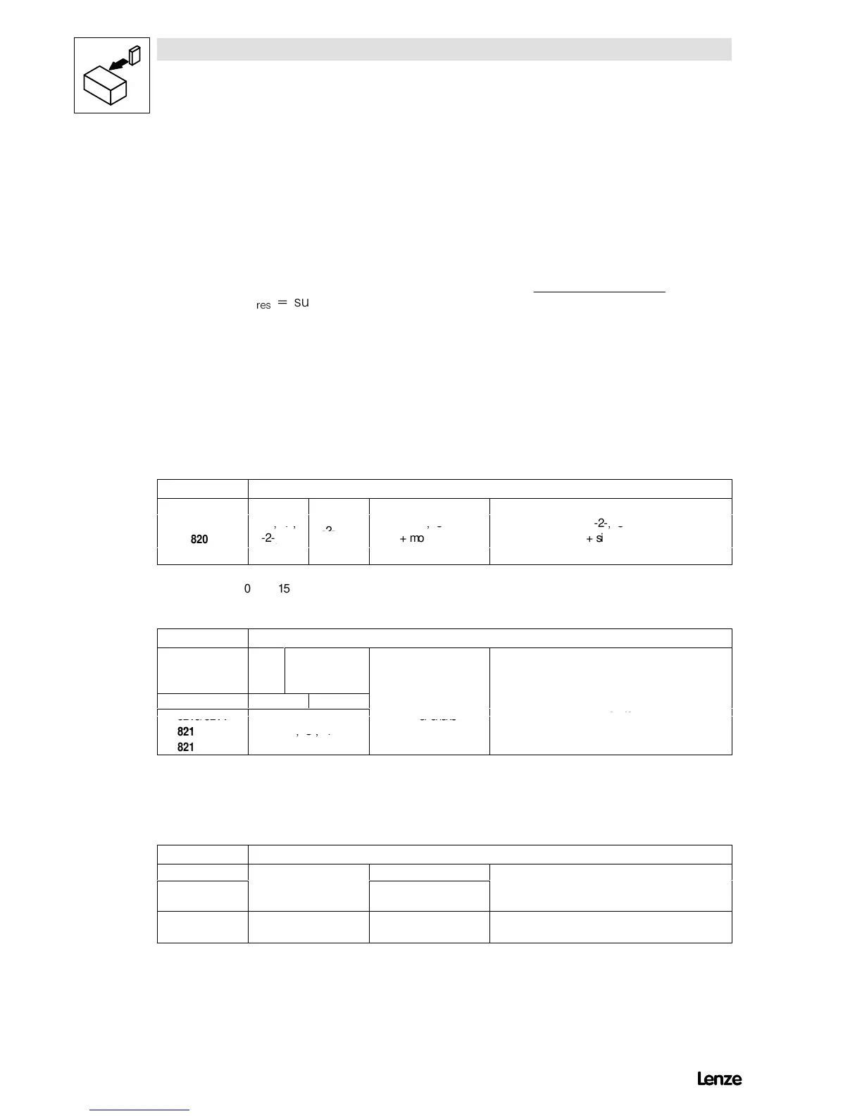
- FIG 4-19 shows the relation between the motor cable length and the
possibly required output filters.
- For group drives (several motors connected to one controller) it is
necessary to calculate the resulting cable length I
res
:
,
UHV
VXP RI DOO PRWRU FDEOH OHQJWKV ô 1R RI PRWRU FDEOHV
¯
- The components stated in FIG 4-19 are valid for chopper frequencies
$ 8 kHz (C018 = -0-, -1-). When using controllers with chopper
frequencies > 8 kHz, different measures may be required. Please contact
Lenze.
- When using unscreened motor cables, the data indicated in FIG 4-19 are
valid for the double motor cable length.
- Please contact Lenze when the absolute or resulting motor cable lengths
are > 200 m.
Type Permissible control mode C014
8201
8202
-0-, -1-,
0 15 25 50 100 200
Motor cable length (resulting), screened in m
Type Permissible control mode C014
8211
-2-,
-3-,
-4-
-2-, -3-
8212 -2-, -3-, -4- -2-, -3-
0 15 25 50 100 200
Motor cable length (resulting), screened in m
Type Additionally required output filters in the motor cable
8221/8222 motor filter/motor choke
(contact Lenze)
8241/8242/8243
8244/8245/8246
none motor filter/motor choke sine filter
0 50 100 200
Motor-cable length (resulting), screened in m
FIG 4-19 Output filters additionally required in the motor cable
Artisan Technology Group - Quality Instrumentation ... Guaranteed | (888) 88-SOURCE | www.artisantg.com