Installation
8200SHB0199
4-31
Types 824X
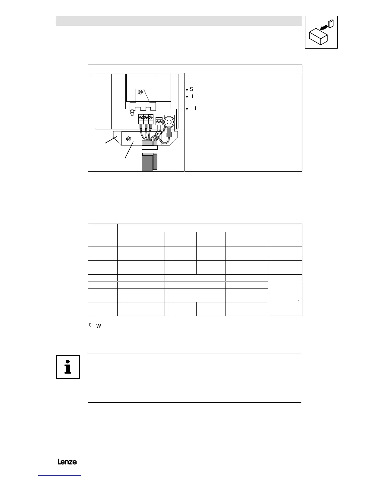
UVW
PE
U
V
W
T1 T2
Correct screen connection with screened cables
(required parts in the accessory kit):
-
Screw sreen plate ➀ on fixing bracket ➁.
-
Fix the screen of the motor cable and thermal contact. Do
not use as a strain relief!
-
To improve the screen connection: Connect the screen
additionally to the stud PE next to the motor connections.
FIG 4-18 Proposal for motor connection with 824X
- Connect the motor cables to the screw terminals U, V, W.
- Observe correct pole connection.
- Max. permissible cable cross-sections and tightening torques
Terminals
Type
Max. permissible
cable cross-sections
U, V, W
PE
connection
Screen/
strain relief
T1, T2
8201 - 8214 2.5 mm
2
0.5 ... 0.6 Nm
(4.4 ... 5.3 lbin)
1.7 Nm
(15 lbin)
- -
8215 - 8218 4mm
21)
0.5 ... 0.6 Nm
(4.4 ... 5.3 lbin)
1.7 Nm
(15 lbin)
- -
8221 - 8223 25 mm
22)
4 Nm (35 lbin) -
8224 - 8225 95 mm
22)
7 Nm (62 lbin) 3.4 Nm (30 lbin)
8226 - 8227 120 mm
22)
12 Nm (106.2 lbin)
M4: 1.7 Nm (15 lbin)
M5: 3.4 Nm (30 lbin)
0.5 ... 0.6 Nm
(4.4 ... 5.3 lbin)
8241 - 8246 4mm
21)
0.5 ... 0.6 Nm
(4.4 ... 5.3 lbin)
3.4 Nm
(30 lbin)
-
1)
With pin-end connector: 6 mm
2
With wire c rimp c ap: 4 mm
2
2)
With ring cable lug: The cross-section is only limited by the cable cut-out in the housing.
Note!
- Switching on the motor side of the controller is permitted
- for safety switch-off (emergency switch-off),
- under load.
Artisan Technology Group - Quality Instrumentation ... Guaranteed | (888) 88-SOURCE | www.artisantg.com