Doc #: L-2600-1023 Page 28 Rev. 02
3.3.1.5 1 Part Detector Edge
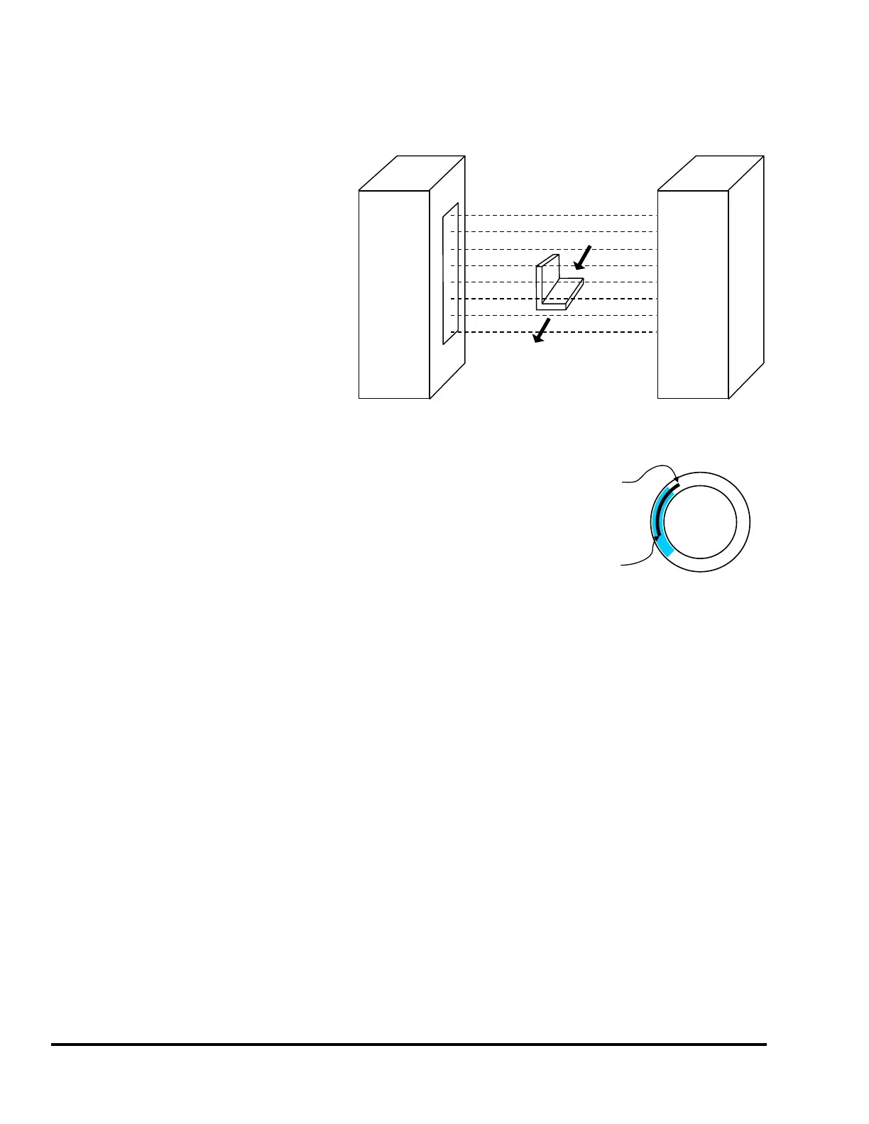
The “1 Part Detector Edge” channel logic
type is used to monitor ejection of parts
that are completely out of the die area as
soon as they are sensed by the channel
input sensor. The channel logic looks for
one part to be sensed during the timing
window. Figure 15 shows and example of
a small part being sensed by an optical
parts detector. When this small part first
interrupts the sensing field of the optical
parts detector it is completely out of the
die area. Detection of the leading edge of
this part ensures that the part is totally out
of the die area.
The “1 Part Detector Edge” channel type functions much like
the “Cyclic” type, the difference being that the timing window
must turn on before, not while, the part is being ejected
(activating the sensor). In other words, this type requires that
the sensor NOT be active when the window turns ON, and
then become active at some point during the window. The
sensor can still be active at the end of the window. With “1
Part Detector Edge”, it is not required that the part completely
passes the sensor by the end of the window. The timing is
shown in Figure 16.
The “Input Type” for the sensor being used to verify part detection can be “Normally Off” or “Normally
On”. The sensor will switch from its normal state when the part is being detected. When a “Normally
Off” sensor is being used to sense part out; the sensor will be “Off” when the part is not in the sensor,
and will be “On” when the part is in the sensor. When a “Normally On” sensor is being used to sense
part out; the sensor will be “On” when the part is not in the sensor, and will be “Off” when the part is in
the sensor.
Small part detected by optical part detector
Transmitter Receiver
Figure 15: “1 Part Detector Edge” Input Example
0
180
90
270
One Part Edge
Part CAN Exit
After Timing Window
(But Does Not Have To)
Part MUST Enter
In Timing Window
Figure 16: Timing Window Example for
a “1 Part Detector Edge” Input