Doc #: L-2600-1023 Page 31 Rev. 02
3.3.1.8 2 Part Detector Pass
The “2 Part Detector Pass” channel
logic type is used to monitor ejection
for two parts detected by a single
sensor. The channel logic looks for
two parts to be sensed during the timing
window, and also looks for the second
part to be past the sensor at the end of
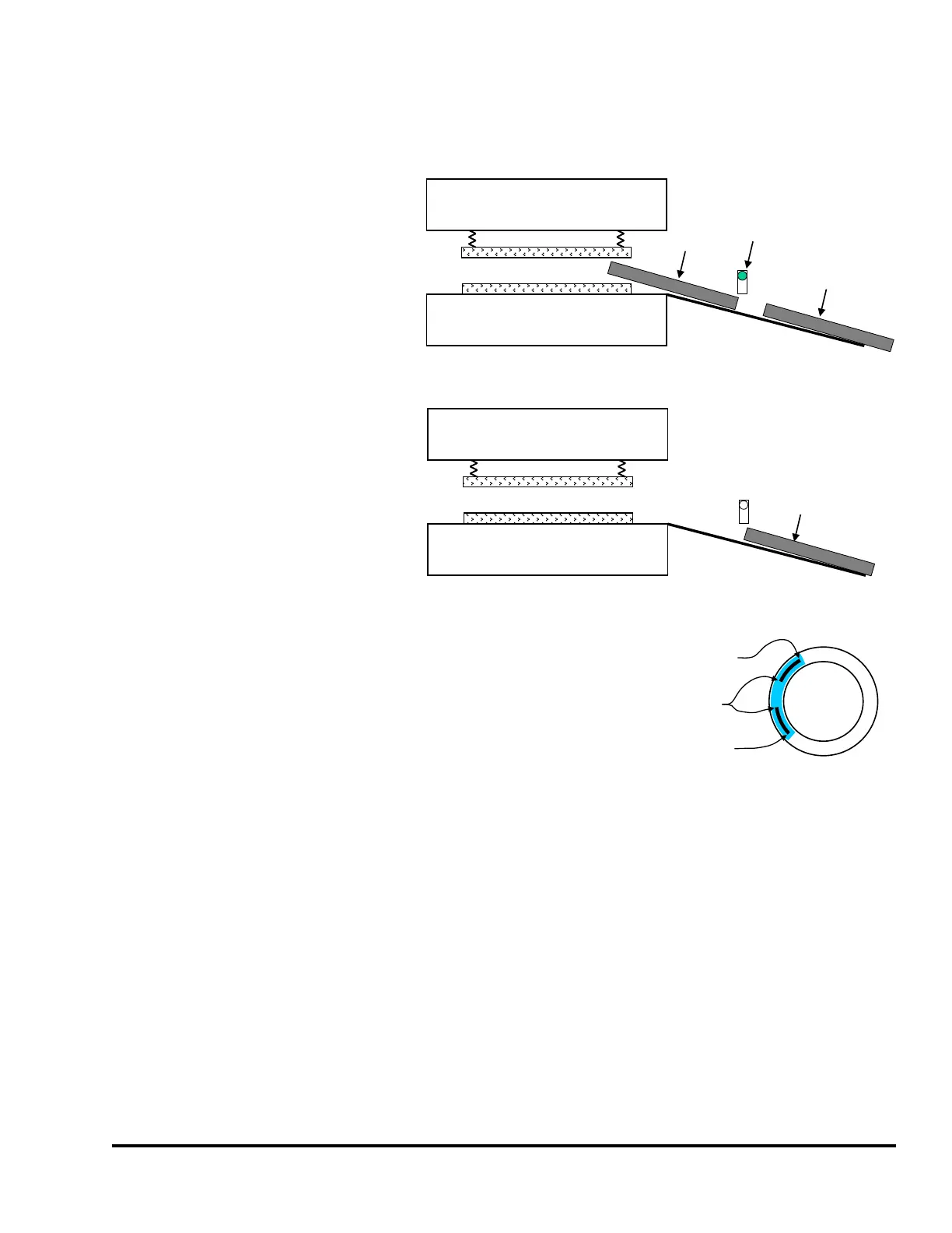
the timing window. Figure 21 shows an
example of two exiting parts sliding
down a chute. When the sensor first
detects the leading edge of the second
part, the trailing edge of the part is still
in the die area. Detection of the leading
edge of this part does not ensure that
the second part is totally out of the die
area. The only way to ensure that the
second part is completely out of the die
is to require that it be completely past
the sensor by the end of the timing
window.
The “2 Part Detector Pass” channel type timing requires that
the input sensor detect both parts during the timing window
only. The sensor cannot detect the presence of a part at the
beginning or at the end of the timing window, but it must
detect the presence of the parts during the timing window. In
other words, the sensor must NOT be active when the window
turns ON, must sense two parts during the window, and must
not be active at the end of the window. There must be a
“Separation Time” between the parts. The first part must
completely exit the sensor before the second part enters the
sensor. The timing is shown in Figure 22.
Note that the sensor is not allowed to become active outside the window or a fault will be generated.
This provides protection against a part ‘bouncing’ on a probe-type detector and satisfying the die
protection input erroneously.
The “Input Type” of the sensor being used to verify part detection can be “Normally Off” or “Normally
On”. The sensor will switch from its normal state when the part is being detected. When a “Normally
Off” sensor is being used to sense part out; the sensor will be “Off” when the part is not in the sensor,
and will be “On” when the part is in the sensor. When a “Normally On” sensor is being used to sense
part out; the sensor will be “On” when the part is not in the sensor, and will be “Off” when the part is in
the sensor.
Upper Die
Lower Die
Second Part
Sensor
First Part
When the leading edge of the second part is first
detected, its trailing edge is still in the die area.
The second part is completely out of
the die area when it passes the sensor.
Second Part
Upper Die
Lower Die
Figure 21: “2 Part Detector Pass” Input Example
0
180
90270
Two Part Pass
Second Part MUST Exit
In Timing Window
First AND Second
Part MUST Enter
In Timing Window
Separation Time
Figure 22: Timing Window Example for
a “2 Part Detector Pass” Input