Doc #: L-2600-1023 Page 42 Rev. 02
channel to “Yes”. In the example of Figure 30, channels 2 and 4 set to automatically bypass in setup
mode.
3.3.6.4 Channel Bypass
Each individual channel can be bypassed. When a channel is bypassed, it no longer monitors its input
sensor. It will not send a stop signal to the press control if the input sensor fails to meet the
requirements of the selected channel type. The “Channel Bypass” column in the screen of Figure 30 is
the same as the “Bypassed” parameter that can be set in the miscellaneous settings screen (see Section
3.3.4.2 on page 39). It is repeated here for the convenience of setting all bypass parameters in one place.
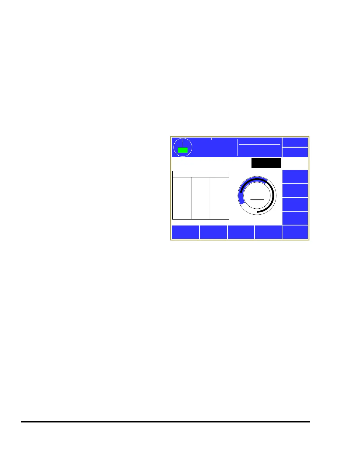
3.3.7 Die Protection Diagnose Screen
Press the Diagnose softkey in the die protection
main screen (see Figure 24 on page 33) to display
the diagnostic screen as shown in Figure 31. This
screen allows the user to diagnose the die protection
channel.
The Previous Channel and Next Channel softkeys
can be used page through the channels without
going back to the Die Protection main screen.
The blue arc in the circular angle display shows the
timing window that is set for the channel, assuming
the “Channel Type” requires one. The black arc in
the circular angle display shows the actual angles
where the sensor was “On” in the selected stroke.
This could be displayed as more than one arc if the sensor turns “On” in multiple places in the stroke.
The captured sensor angles are automatically updated every stroke. An “Angle Cursor” is displayed on
the circular display and is controlled by the Decrement Cursor and Increment Cursor softkeys. A
numeric readout of the cursor angle is shown in the center of the circle.
At the top of the screen the actual input state of the channel is displayed (“On” or “Off”). Below that is
the number of “in window” transitions that occurred the last time through the timing window (or the
current number of transitions if currently inside the window). This can be of help in diagnosing sensor
bounce or setting separation times when using 2 part detector channel types.
On the left side of the screen is a list of “On:Off” angle pairs for the currently displayed stroke. Each
entry in this list represents an event where the sensor turned on and back off. These are numeric values
that correspond to the black arc or arcs that are shown in the circular display to the right.
When this screen is entered, the default display is the last full stroke (0 to 359 degrees). This means that
if the current crank angle is at 45 degrees, the display is showing the data from the stroke before. The
Decrement Stroke and Increment Stroke softkeys are used to change the stroke that is shown on the
screen. This can range from the current stroke (0 degrees to the current angle) to as many as about 20
strokes back. The exact number of strokes back that can be viewed is dependent on the number of
transitions that have occurred per stroke. The system stores the last 64 on/off transitions.
359
TOP
Stroke Speed
0
SPM
ACC
Espanol
Exit
Die
Protection
Overlay
Strokes
Previous
Channel
Next
Channel
Increment
Cursor
Decrement
Cursor
Increment
Stroke
Decrement
Stroke
Die Prot.
Channel 3
0
270
180
90
Angle
Cursor
0°
Input:
In Window Transitions:
Stroke Shown: Last Full Stroke
Capture Angles (On:Off)
279:181
Off
1
Mode:
Production
Figure 31: Die Protection Diagnose Screen