Doc #: L-2600-1023 Page 80 Rev. 02
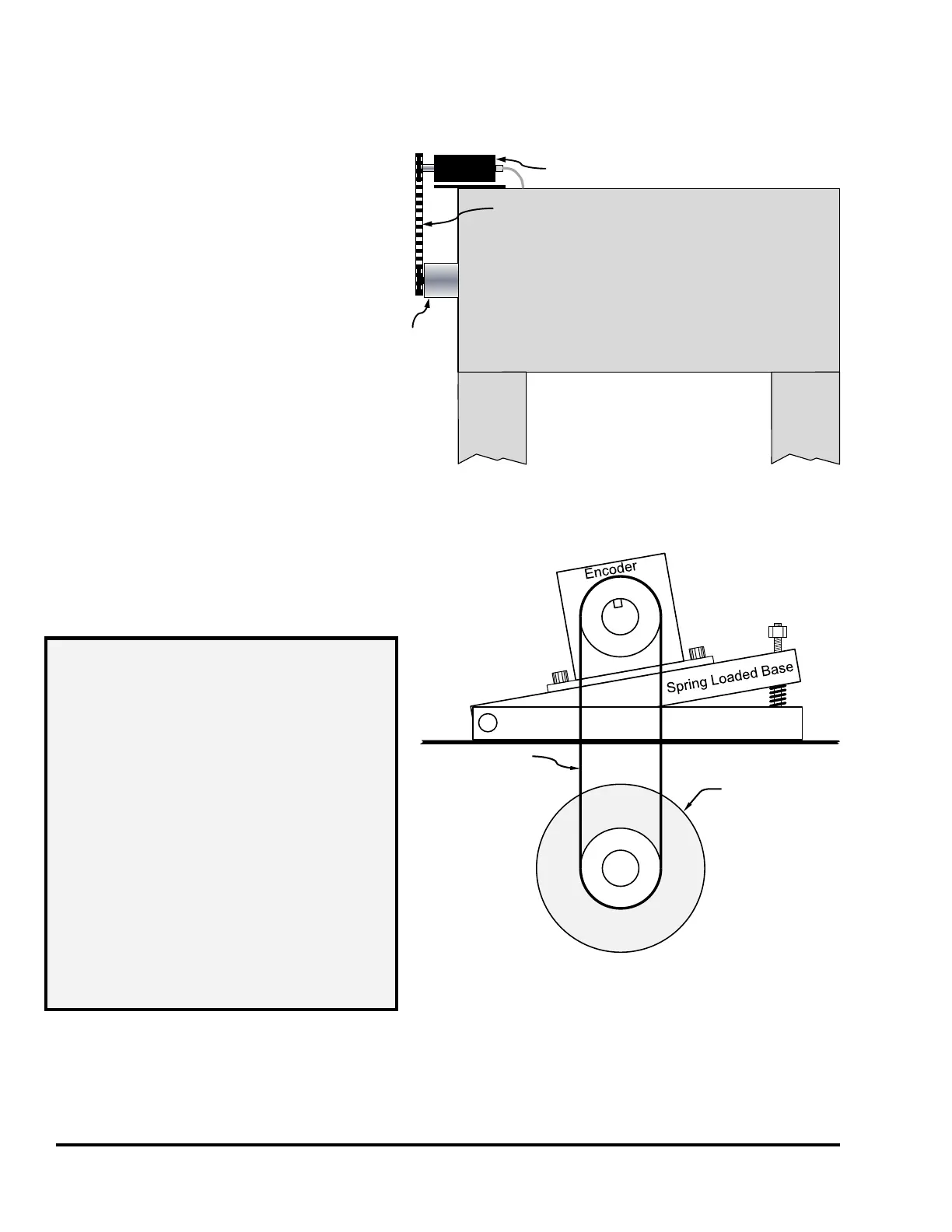
7.3 Mounting the Encoder
The System 2600 requires a Link
5100-11 encoder to get angle
information from the crankshaft or
eccentric.
The encoder may be direct driven by a
coupling off the center of the shaft or
driven by a chain or timing belt as
shown in Figure 70.
Chain and sprockets may have been
purchased from Link Systems. If so,
the sprockets will be 35B28 (28 teeth)
and chain will be size 35 roller chain.
Link suggests that, if the customer
provides chain and sprocket, the same
type be used. The electronic offset
capability (see Section 4.3.2 on page 57) during calibration can correct mechanical misalignment.
A spring-loaded mounting base (see Figure
71) will be supplied when the encoder will be
chain driven to maintain chain tension.
The 5100-11 encoder shaft is 3/4 inches in diameter with a 3/16 inch wide by 1 inch long standard
keyway. The sprocket attached to the encoder must be bored and keyed to fit. Do not install the
sprocket without a proper size key. After installing sprocket and key, the clip ring must be installed in
the groove on the end of the resolver shaft.
Press
Crown
Crank or
Eccentric
Shaft
Resolver or
Encoder
Chain or
Timing Belt
A chain guard is
necessary to meet
OSHA 1910.219
Standards
Note:
Figure 70: Resolver Mounting to Shaft
Crank or
Eccentric
Shaft
Chain
Figure 71: Encoder on Spring Base
NOTE: The encoder must be driven on
a one-to-one basis with the
press. That is, one stroke of the
press must result in exactly one
turn of the encoder. If you have
a press that only provides access
to an intermediate shaft or back
shaft for connection of the
encoder, you will have to
determine how many turns this
shaft makes for each turn of the
crank or eccentric shaft. You
must then use sprockets of
different size, chosen to provide
one turn of the encoder for one
turn of the crank or eccentric
shaft.