Doc #: L-2600-1023 Page 83 Rev. 02
7.4 Installing the 805-3 Communications Card
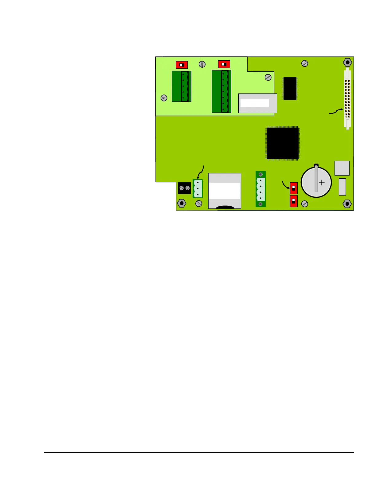
The optional 805-3
communications board mounts on
the circuit board in the door of the
System 2600 as shown in Figure
74. Carefully mate it to the
matching connector on the 1200-1
board and secure it with 3 6-32 X
1/4" screws.
If properly installed, the System
2600 will automatically detect the
board. A quick check is to see if
the Ethernet Diagnostics softkey is
present in the main diagnostics
screen as shown in Figure 40 on
page 53. Pressing that key will
bring up a screen that shows the
state of the Ethernet connection,
the MAC address of the unit, and
other diagnostics related to this
board.
SD CARD
PUSH TO INSERT
PUSH TO EJECT
TX
RX
G
1200-1 Board
USB
USB
CR2477
Battery
SHLD
GND
CANH
CANL
PORT 1
Ribbon Cable
Connector
(to 1200-2 Board)
ETHERNET
PORT 3
PORT 2
ISO GND
+R
-R
+T
-T
-T
+T
-R
+R
GND
RX
TX
805-3 Comm.
Card
Touch
Screen
Cal Switch
Figure 74: 805-3 Comm. Board Mounting