Doc #: L-2600-1023 Page 57 Rev. 02
4.3 Encoder Settings Configuration Screen
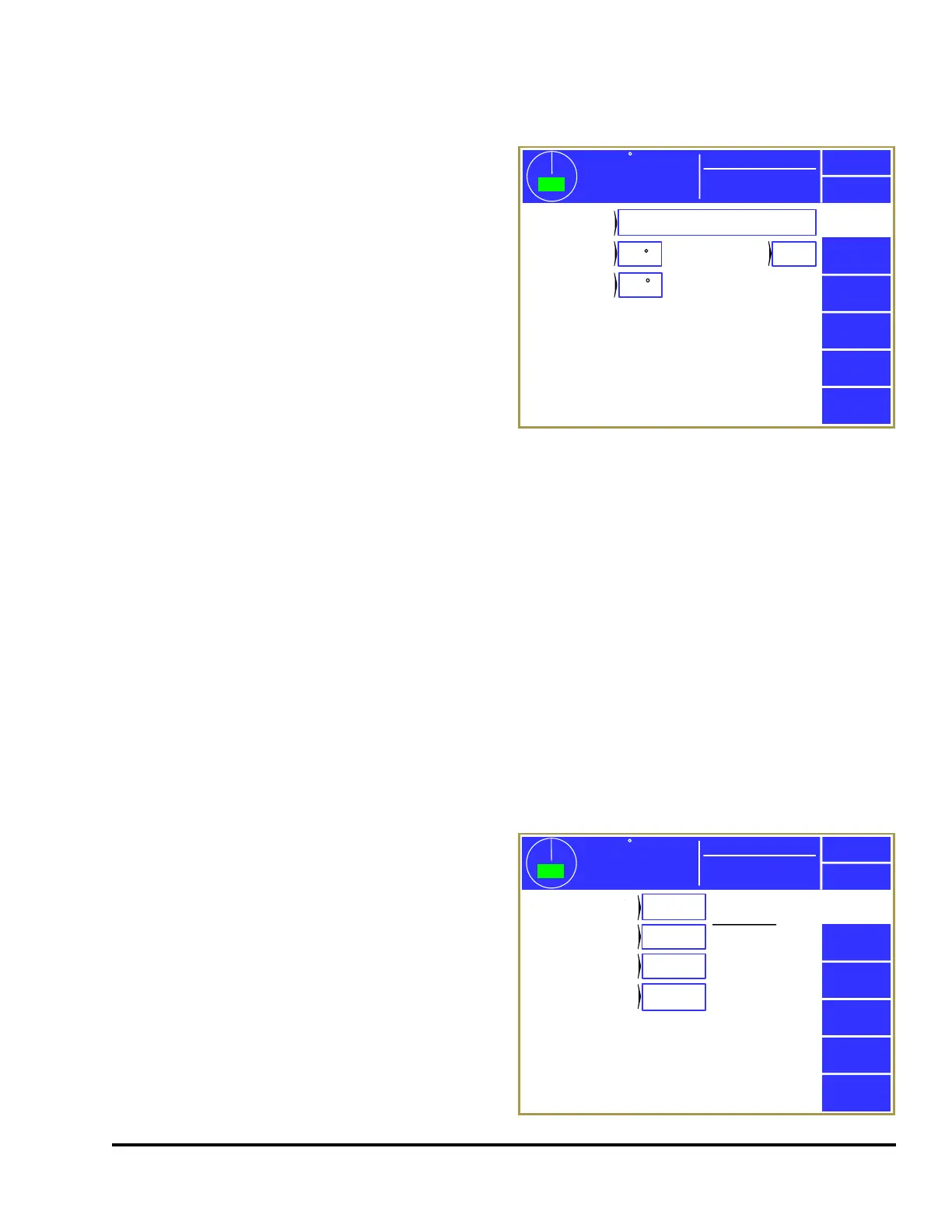
Press the Encoder Settings softkey in the main
configuration screen as shown in Figure 43 to
display the screens shown in Figure 45.
4.3.1 Trigger Mode
This parameter is fixed as “Link 5100-11 Rotary
Transducer” and cannot be changed.
4.3.2 Encoder Offset
This parameter is used at installation to set the zero
position of the encoder at the top of the stroke. The
offset can be entered directly, or the press can be
positioned at the top of the stroke and Set Zero
selected or at the bottom of the stroke and Set 180 selected. These softkeys will select the proper
encoder offset value to make the current reading 0 degrees or 180 degrees respectively.
4.3.3 Encoder Reversed
This parameter allows flexibility when mounting the crankshaft transducer by allowing it to turn
counter-clockwise when the press is running in the forward direction if set to “Yes”.
4.3.4 Crankshaft Hysteresis
This parameter controls how much in the opposite direction from the initial direction of travel the
crankshaft must move before the system allows the reading to change or “go backwards”. It is used to
prevent false triggering of limit switch and die protection windows when the press is right on the edge of
a window and the reading varies due to vibration and/or chain or coupler slack. 5.0 degrees is normally
a reasonable value and this should only be changed if instructed by Link technicians.
4.4 RUN (Clutch/Brake) Input Settings Configuration Screen
Press the RUN (Clutch/Brake) Input Settings
softkey in the main configuration screen as shown
in Figure 43 to display the screens shown in Figure
46.
The System 2600 can optionally use a motion
detection system to detect coupling failures that
result in the encoder not being driven by the
crankshaft. If encoder decoupling occurs, the
system cannot perform its monitoring and control
functions that depend on crankshaft angular
position. The motion detector generates an
immediate stop signal if it senses motion below the
SPM (strokes per minute) configured in the
0
Exit
359
TOP
Stroke Speed
0
SPM
ACC
Espanol
Link 5100-11 Rotary Transducer
0
5.0
Mode: Production
Die
Protection
Set Zero
Set 180
Trigger
Mode
Encoder
Offset
Crankshaft
Hysteresis
No
Encoder
Reversed
Figure 45: Encoder Settings Screen
0
Exit
359
TOP
Stroke Speed
0
SPM
ACC
Espanol
Yes
125 ms
3 SPM
50 ms
Mode: Production
Die
Protection
Use RUN
(Clutch/Brake) Input
Engagement
Time Limit
Motion
Threshold
Loss of
Motion Time
Last Actual
105 ms
Figure 46: RUN Input Settings Screen