Doc #: L-2600-1023 Page 92 Rev. 02
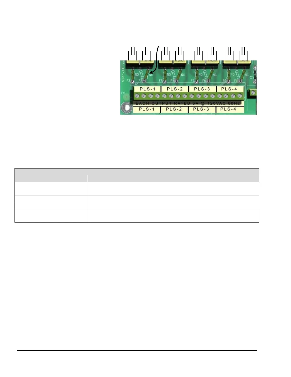
Figure 85 shows the contact arrangement
of the electromechanical limit switch
outputs with each output having two
normally open outputs. One of the outputs
on each channel can be turned into a
normally closed contact by moving a pico-
fuse as illustrated on the circuit board.
Solid-state relay output modules are available for PLS 1-4 and PLS 5-8. These are often necessary for
higher speed presses, for applications where no contact bounce can be tolerated, or for applications that
require very short turn-on periods (<50 milliseconds). These relay modules have provisions for 4 solid-
state relays that can be populated individually as AC or DC types. These modules are daisy-chained in
the same manner as described for the electromechanical types.
Relay Module Specifications
Electromechanical Relay
Contact Rating
120 VAC Max, 5 Amps
30 VDC Max, 5 Amps
24 to 120 VAC Max, 3 Amps @ 45º ambient, 2 Amps @ 70º ambient
60 VDC Max, 3 Amps @ 45º ambient, 2 Amps @ 70º ambient
Relay Contact Fuse (all relay
types)
Littlefuse 0251007 (7 Amp, 125V AC or DC, Fast Blow)
NO/NC
Select
Each contact rated 5 amps
At 120VAC or 30VDC
Figure 85: Limit Switch Outputs