Doc #: L-2600-1023 Page 38 Rev. 02
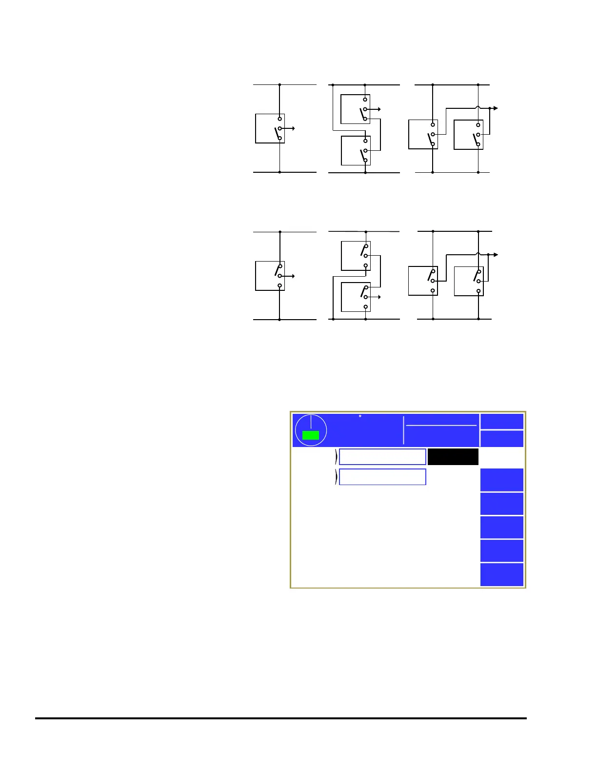
Figure 27 shows single, series, and parallel
connections for both NPN and PNP solid
state sensors. Normally only one sensor is
wired to an individual input. This is
preferred as it enables individual
diagnostics for each sensor. However,
multiple sensors can be wired in series or
parallel to expand monitoring capabilities.
When solid state sensors are wired in series
or parallel, they must be of the same type.
Do not mix NPN and PNP sensors when
wiring them in series or parallel. When
wiring solid state sensors in series, ensure
that the total voltage drop across all sensors
does not exceed the value mentioned above.
Also, the power up delay for each sensor
must be considered since the last sensor in
line is not powered until the upstream
sensor is closed. When wiring solid state
sensors in parallel, the total leakage currents
of all sensors must not exceed the maximum
leakage current given above.
3.3.4 Die Protection Channel Miscellaneous Settings Screen
Touch inside the miscellaneous settings area (see
“a” in Figure 26) to enter the miscellaneous settings
screen for the channel. The number and type of
parameters in this screen vary depending on the
“Channel Type” selected for the channel. The
screen shown in Figure 28 is a typical example for
an “In Position” channel. The following
subsections describe the parameters that may show
up in this screen.
3.3.4.1 Stop Type
This selects the type of stop that should be
generated if the die protection logic for the channel
is not satisfied (i.e. there is an error). The available
stop types for die protection channels are
“Immediate Stop” and “Top Stop”. See Section 2.1 on page 9 for details on these stop types. The user
must select a stop type appropriate for the process.
V+
SIGNAL
COM
V+
SIGNAL
COM
V+
SIGNAL
COM
V+
SIGNAL
COM
24 VDC
0 VDC
TO INPUT
NPN CONNECTIONS
V+
SIGNAL
COM
V+
SIGNAL
COM
V+
SIGNAL
COM
V+
SIGNAL
COM
24 VDC
0 VDC
TO INPUT
SERIES PARALLEL
PNP CONNECTIONS
24 VDC
0 VDC
TO INPUT
SERIES
V+
SIGNAL
COM
V+
SIGNAL
COM
V+
SIGNAL
COM
V+
SIGNAL
COM
24 VDC
0 VDC
TO INPUT
PARALLEL
V+
SIGNAL
COM
V+
SIGNAL
COM
V+
SIGNAL
COM
V+
SIGNAL
COM
V+
SIGNAL
COM
V+
SIGNAL
COM
24 VDC
0 VDC
TO INPUT
SINGLE
TO INPUT
24 VDC
0 VDC
SINGLE
V+
SIGNAL
COM
V+
SIGNAL
COM
Figure 27: Wiring Sensors in Series and Parallel
359
TOP
Stroke Speed
0
SPM
ACC
Espanol
Exit
Die
Protection
Die Prot.
Channel 3
Stop
Type
Immediate
Bypassed
No
Mode:
Production
Figure 28: Die Protection Channel Misc. Settings