Doc #: L-2600-1023 Page 87 Rev. 02
When using AC Power, use the L1, L2 and PE
terminals (See Figure 76).
When using +24VDC Power, use the +24, GND, and
PE terminals.
The power wiring should be at least 16 GA.
There is an amber LED indicator which indicates
that an internal power supply is functioning. This
indicator should always be lit as long as power is on.
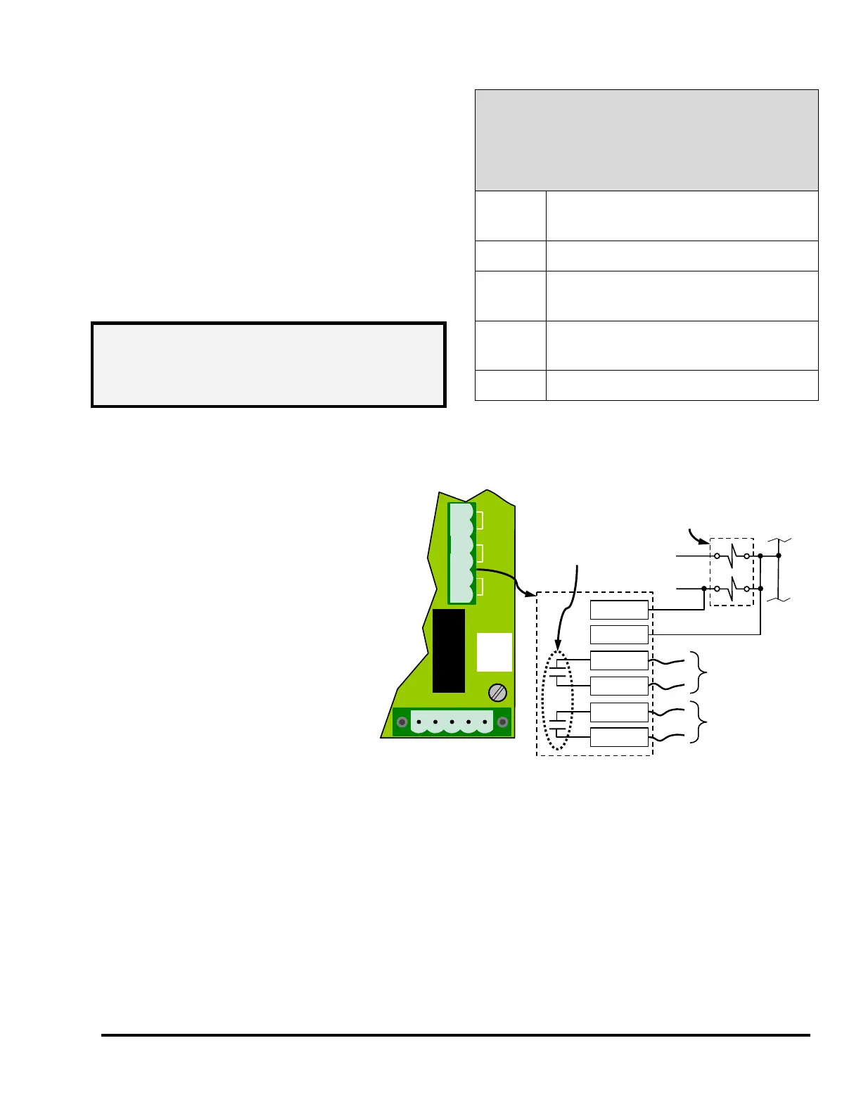
7.5.3 Wiring the Stop Outputs
Normally open electromechanical
relay contact outputs are provided for
sending stop signals to the press
control. See the “Run/Stop
Connector” on Figure 76 for the location
of the connector. A separate Top Stop
output (T-Stop, terminals 3 and 4) and
Immediate Stop output (E-Stop,
terminals 1 and 2) are provided. Each
output is rated for a maximum of
250VAC or 30VDC at 5Amps, and is
NOT fused internally.
Figure 77 shows the connector pint
numbers of the stop connector and the
way the relay contacts are arranged.
Pull the wires in the appropriate conduit (low or high voltage depending on the circuit voltage) between
the System 2600 enclosure and the press control.
7.5.4 Wiring the RUN (Clutch/Brake) Input
In the case of Mechanical Presses, the System 2600 can optionally use a signal from the press
clutch/brake control that indicates when the press clutch is engaged (the press is stroking). This signal is
derived from the voltage across the dual air valve solenoid (in some cases a hydraulic valve may be
used) that controls stroking and may be 24VDC or 120VAC.
Power Connections for the
System 2600
(See Figure 76 for
Power Connector Location)
90-260 VAC Line
17 VA (0.15 Amp at 120 VAC)
Protective Earth (used with both AC
and DC input power)
+24VDC +/- 10% Input Power
(0.4 Amps)
NOTE: PE (Protective Earth) should be
grounded when using AC or DC
power. It is the only connection used
with either power source.
4
1
3
2
TS
ES
TS
ES
To Press Control
Top Stop Circuit
To Press Control
Immediate Stop
Circuit
Each relay contact
rated 250VAC or
30VDC at 5 Amps
FUSE 5X20
L1
L2
PE
+24
GND
T-STOP
E-STOP
RUN
1 2 3 4 5 6
5
RUN
6RUN
Clutch/Brake
Dual Air Valve
(24 VDC or 115 VAC)
Figure 77: Breakaway of Run/Stop Connector