Doc #: L-2600-1023 Page 53 Rev. 02
3.6 The Diagnose Screen
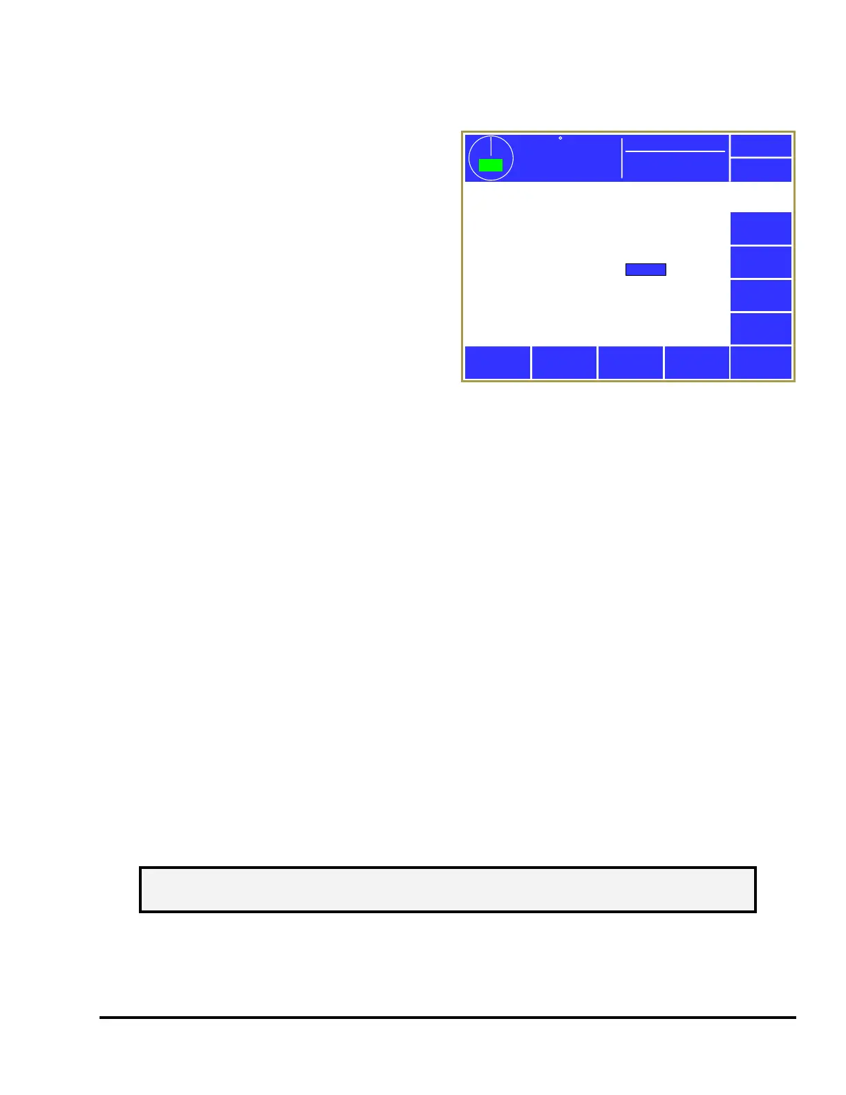
Pressing the Diagnose softkey in the main screen
will bring up the diagnostic screen shown in Figure
40. Some of the information in this screen is used
by Link personnel for telephone troubleshooting,
but the following items are of general interest:
Inputs 0 to-5 – Shows the status of the 5 inputs (I0,
I1, I2, I3, I4, and I5) that are located at the bottom
of the System 2600 enclosure. Depending on the
configuration, these inputs can be used to indicate
setup mode or other future uses. The text at left of
each input will indicate its currently configured
function.
Top Stop Relay – Shows the On/Off status of the
top stop relay. Note that “On” indicates the System 2600 is NOT asserting a top stop.
Immediate Stop Relay – Shows the On/Off status of the immediate stop relay. Note that “On” indicates
the System 2600 is NOT asserting an immediate stop.
Run/Program Key – Show the position of the RUN/PROG key on the front of the operator terminal.
Use this to verify that the key switch is operating correctly.
SD Card Detected and SD Card OK – These two lines show whether an SD Card is inserted into the SD
Card slot of the operator terminal and, if inserted, whether the card has been successfully read.
Battery Voltage – The operator interface uses one CR2477 coin cell battery to maintain its calendar/time
functions and a small amount of battery backed memory. This voltage of a new battery should be
slightly more than 3 volts. This value will be shown in yellow when the voltage drops below 2.4 volts
and in red when it drops below 2.19 volts. Most settings are stored in flash memory and are not lost
when the battery fails, but some things that are updated very rapidly (like the current counter values) are
written into battery backed RAM. If, after powering down and back up, the counter values are 0, then
check this readout and replace the battery if needed.
3.6.1 Ethernet Diagnostics
Pressing the Ethernet Diagnostics softkey in the screen of Figure 40 will bring up a screen that shows
information about the current state of the Ethernet connection.
The information near the top of the screen shows the Host Name of the operator terminal and whether or
not there is an active Ethernet connection. An active connection is when there is an Ethernet cable
plugged into the Ethernet jack AND the other end of the cable is connected to an active hub or switch.
Most of the other information shown on this screen are standard Ethernet settings that can be used by
Exit
Encoder
Diagnostics
Setup Mode (Input I0):
(Input I1):
(Input I2):
(Input I3):
(Input I4):
Off
Off
Off
Off
Off
Run/Program Key:
SD Card Detected:
SD Card OK:
Screen Cal Switch:
Battery Voltage:
Run
No
No
No
3.02
SD Card
Diagnostics
OIT Info
OIT
Diagnostics
359
TOP
Stroke Speed
0
SPM
ACC
Espanol
Top Stop Relay:
Immediate Stop Relay:
Off
On
Event Log
Mode: Production
Ethernet
Diagnostics
Figure 40: Main Diagnostic Screen
NOTE: The Ethernet Diagnostics softkey and screen will only appear if the optional
communications card is installed.