Doc #: L-2600-1023 Page 27 Rev. 02
“Window Off” angle should be set to a point after the material has been fed into place. If the material is
not in position by the end of the timing window, a fault will be generated. The “Window Off” angle
must also be set so that the fault will stop the press before the die closes enough to cause damage.
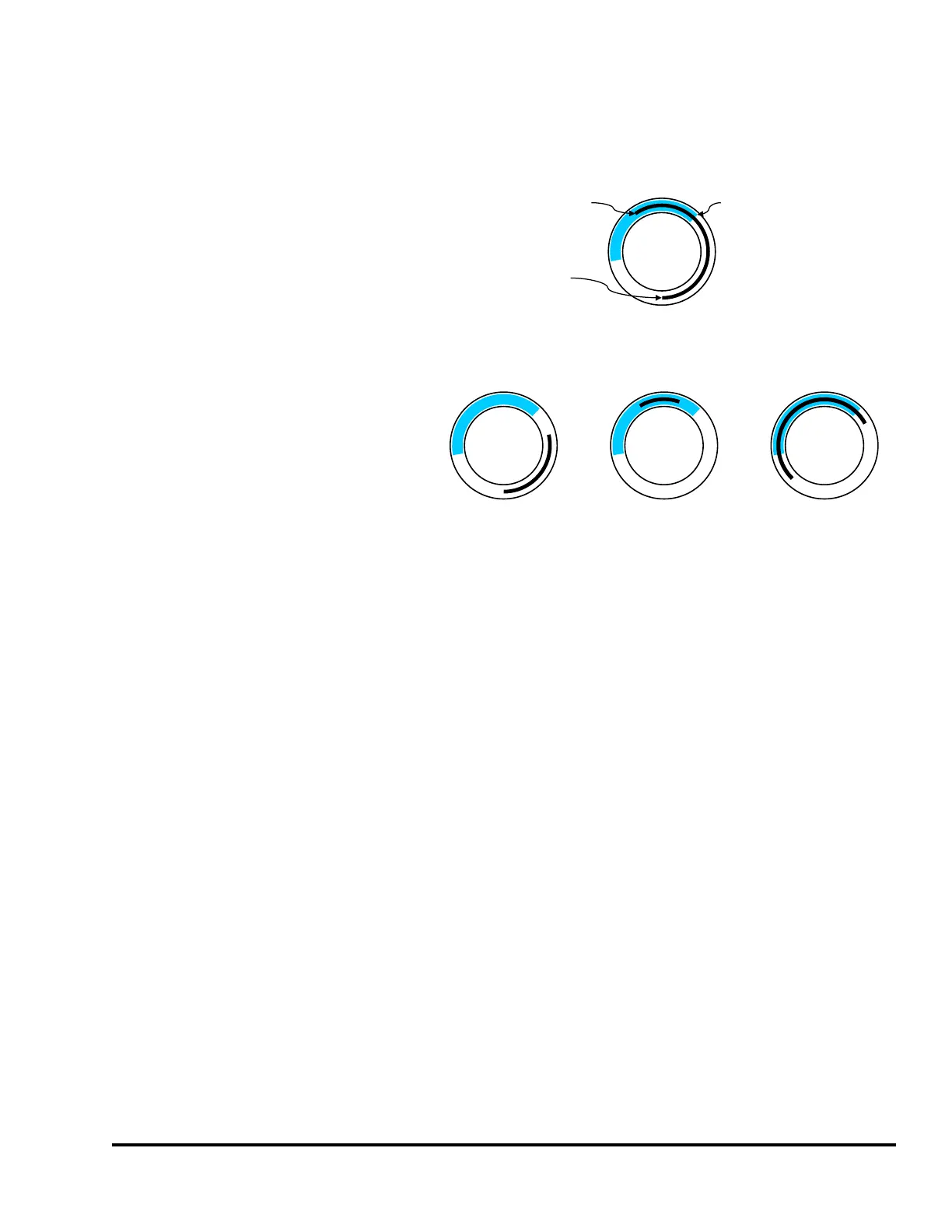
An illustration of the In Position timing
sequence is shown in upper part of
Figure 14. This figure shows that the
material was fed into place during the
timing window and that the material
was in place at the end of the timing
window.
Figure 14 also shows some
unacceptable conditions for In Position
events. There are three unacceptable
conditions shown. The left
unacceptable condition shows that the
feed was not in place at the end of the
timing window. The center
unacceptable condition shows that the
material did arrive in place during the
timing window, but was not in place at
the end of the window. As shown in
Figure 13, this condition could occur in overfeed situations. The right unacceptable condition shows that
the material was sensed as being in position before the beginning of the timing window. All of these are
fault conditions.
The “Input Type” of the sensor being used to verify material position can be “Normally Off” or
“Normally On”. The sensor will switch from its normal state when the material is in position. When a
“Normally Off” sensor is being used to sense material position; the sensor will be “Off” when the
material is not in place, and will be “On” when the material is in place. The example illustrated in
Figure 13 is an example of a “Normally Off” sensor. When a “Normally On” sensor is being used to
sense material position; the sensor will be “On” when the material is not in place, and will be “Off”
when the material is in place. An example of a “Normally On” application is detecting proper material
position by looking for a hole in the material. The sensor is “On” when there is material over the sensor.
The sensor will switch to “Off” at the proper feed position when the hole is over the sensor.
3.3.1.4 In Position Inhibit
“In Position Inhibit” operates the same as “In Position” but with the additional characteristic that when
the press is stopped inside the timing window, it will assert a stop until the sensor turns on. In other
words, it will not allow the press to start until the sensor is made. When the press is running, it operates
exactly like “In Position”. This mode is especially handy when the press is running in Single Stroke
with a long and/or slow feed progression as it prevents the next stroke until the material is in place.
Otherwise, it might be possible to “false start” and hit the end of the timing window before the material
has fed up – which will then cause a stop in the downstroke. Also see section 4.2.5 on page 56 for more
information on how inhibit behaves and the considerations for its use.
0
180
90
270
0
180
90
270
0
180
90270
0
180
90
270
Acceptable
Unacceptable
New Material Fed
Into Position
Feed Checked
Material Cut
Away By Die
Figure 14: Timing Window Examples for an “In Position” Input