Doc #: L-2600-1023 Page 88 Rev. 02
Two wires must be pulled through the appropriate conduit (low or high voltage depending on valve
solenoid voltage) between the press control and the System 2600. On the press control end the wires
must be connected to opposite sides of one solenoid of the dual air valve as shown in Figure 77. On the
System 2600 end, the wires must be connected to terminals 5 and 6 of the “Run / Stop Connector” (See
Figure 76 to locate this connector). Note that the RUN input connections are NOT polarized, either
side of the air valve can be connected to either RUN input connection.
Some presses have a single dual air valve that operates both clutch and brake. Others have two dual air
valves, one for the clutch and one for the brake. When two dual air valves are used, always wire to a
solenoid for the valve that controls the clutch.
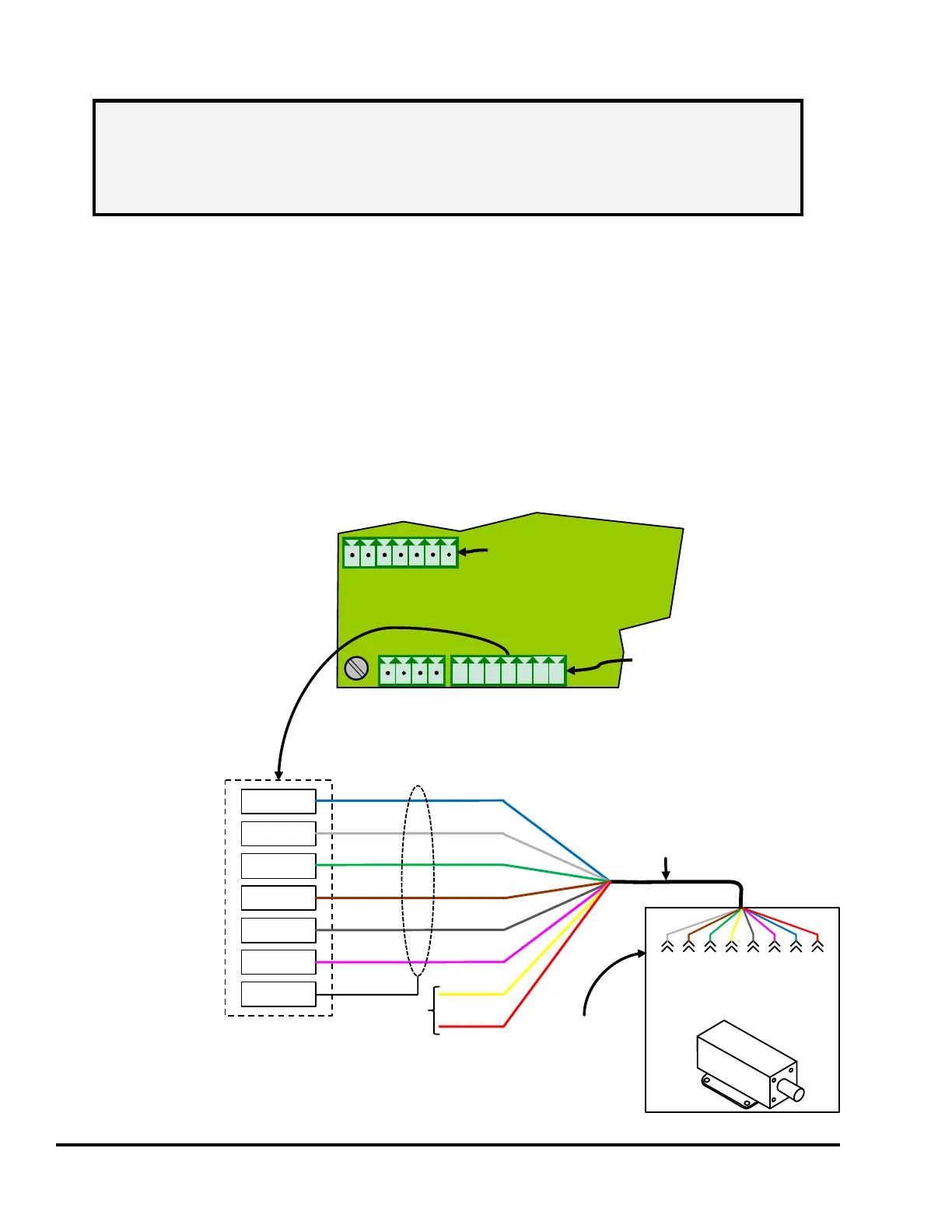
7.5.5 Wiring the 5100-11 Rotary Transducer
The 5100-11
encoder is used with
the System 2600 to
provide crankshaft
angle and speed.
A standard M12-8
cordset is used to
connect to the
encoder and should
be run in conduit.
Figure 78 shows
how the M12-8
cordset should be
wired to the System
2600 encoder
connector.
NOTE: While this input is optional, it is recommended to use it when possible. This
enables the system to detect coupling failures that result in the encoder not being
driven by the crankshaft. If encoder decoupling occurs, the system cannot
perform its monitoring and control functions that depend on crankshaft angular
position. See section 4.4 on page 57 for details.
Auxiliary
Inputs
Connector
+24V
GND
I1
I2
I3
I4
I5
Encoder
Connector
+24V
GND
+R
-R
+T
-T
SH
7 Power
BrownData+
GrayData-
PinkGround
GreenCLK-
WhiteCLK+
BluePower
8 NC
4 NC
1 CLK+
3 CLK-
2 DATA+
5 DATA-
6 Ground
Yellow
Red
No Connect
Color code is typical for
M12-8 cordset, but may
vary by manufacturer
Straight run to
5100-11 Encoder
M12-8 pinout
for Link
5100-11
rotary
transducer.
1
2
3
4
5
6
7
+24
-T
+T
+R
-R
GND
SLD
1 2 3 4 5 6 7
+RY
CRY
BRY
ARY
Figure 78: 5100-11 Encoder Connections