Doc #: L-2600-1023 Page 78 Rev. 02
7.2 Mounting the System 2600
The System 2600 comes in an enclosure ready to bolt on to the machine.
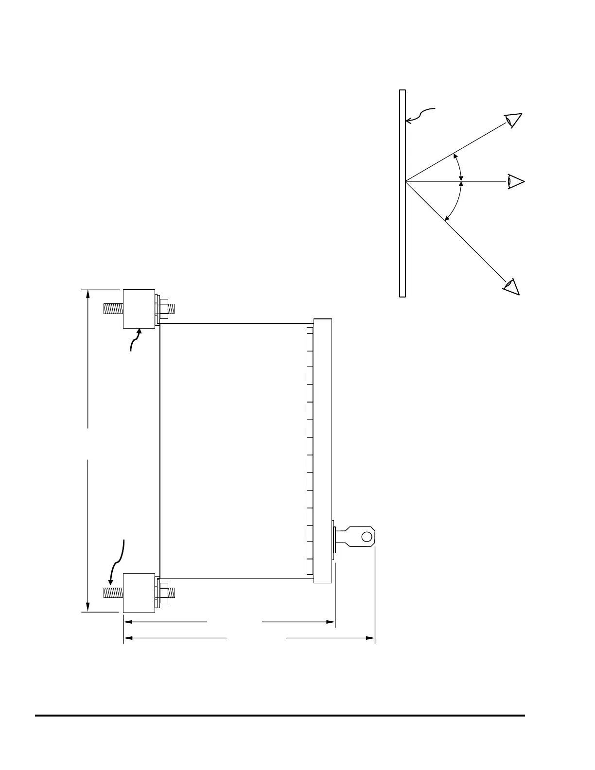
Consideration should be given to the viewing angle of the operating
personnel. Figure 67 shows the most usable viewing angles for the LCD
display used in the Link OIT - about 30 degrees “above” to 45 degrees
below is preferable. Going further in either direction by about 20 degrees
is possible, if absolutely necessary. Viewing the operator terminal from
slightly “below” it generally results in the best display quality.
Also note that the door on the System 2600 enclosure opens to the left
when viewing the unit from the front. Make sure the unit is mounted in a
location that allows the door to open as access will be required for wiring
and maintenance activities such as firmware updates.
The dimensions and
mounting requirements for
the System 2600 are shown
in Figure 68 and Figure 69.
Figure 68 shows a side view
when using the provided
shock mounts which should
be used when mounting the
System 2600 to the press
frame.
Five knockouts on the
bottom side of the enclosure
are provided that will
accept 1/2 inch cord grip or
Seal-Tite connectors.
Power, Top Stop, and
Immediate Stop
connections should be
wired through the knockout
on the right. Strain gauge
wires should not be routed
along with any other signal.
Figure 67: OIT Viewing
Values in parentheses
are in millimeters
8.25”
(210)
5.4” (137)
6.4” (163)
1/4-20 X 1/2”
Shock
Mount
(4 places)
Figure 68: Enclosure Dimensions Side View with Shock Mounts