Doc #: L-2600-1023 Page 81 Rev. 02
Another sprocket must be attached to the machine shaft. The proper size hole must be drilled and
tapped in the static center of the machine shaft. After attaching the sprocket to the shaft, an additional
hole should be drilled approximately 3/4 inch off of the static center. This hole should be drilled
through the sprocket and into the machine shaft. The sprocket should be removed and the off-center
hole in the machine shaft tapped for a 1/4 inch bolt or larger. The off-center hole in the sprocket must
provide proper clearance for the bolt. Attach the sprocket to the machine shaft with the center bolt and
the off-center bolt. When attaching the chain to the sprockets, it is not necessary for the zero position of
the encoder to be aligned with the top dead center of the machine shaft. The system allows the user to
program an offset value to make up the differences between the machine top dead center and encoder
zero.
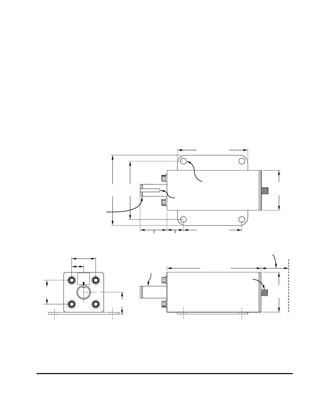
The following show dimensions for the 5100-11 as well as mounting dimensions when used in
conjunction with the spring base.
C
L
C
L
1.50” (38.1)
1.37”(34.8)
0.75” (19.1)
1.50”
(38.1)
1.015”
(25.8)
3.67” (99.2)
1.7”
(43.2)
Shaft
0.75” (19.1)
diameter
2.50”
(63.5)
5.9” (149.0)
0.375” (9.5)
diameter
(4 places)
2.50”
(63.5)
3.67”
(93.2)
4.40”
(111.8)
Circular
Connector
Allow 3.0” (76)
clearance for
mating connector
4.40” (111.8)
Values in
parentheses
are in millimeters
TOP
SIDE
3/16” (4.8) wide
by 1” (25.4) long
standard keyway
Clip Ring
Groove
5100-11
Encoder
Figure 72: 5100-11 Encoder Dimensions