Doc #: L-2600-1023 Page 21 Rev. 02
3.2 Main Operator Terminal Screen
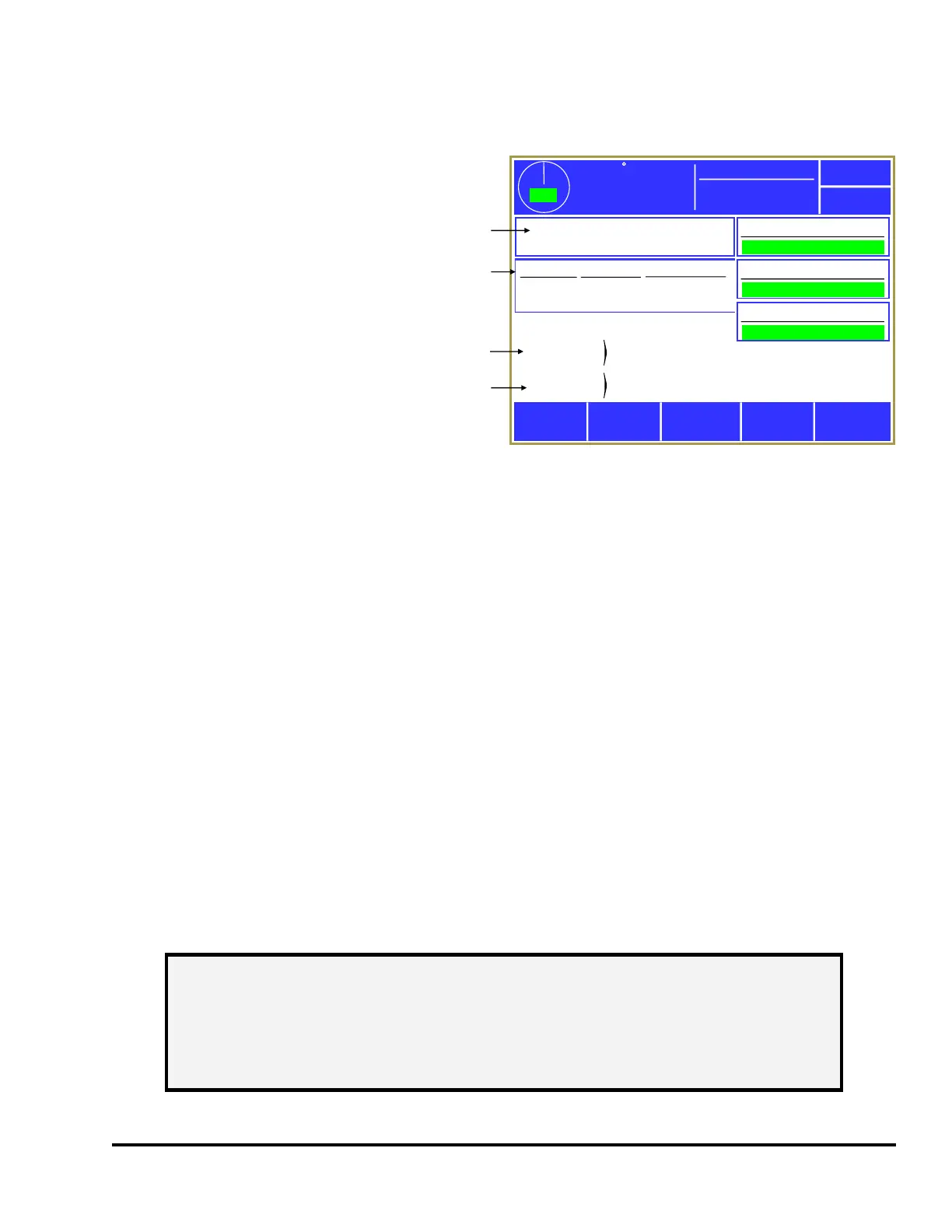
The operator interface main screen shown in
Figure 8 provides the current status of the
System 2600 overall and indicates if
attention is required. This is the initial
screen displayed when the unit powers up.
From this screen the operator may navigate
to Die Protection, Limit Switch, Job Setups
(see “a” in Figure 8) or Counters (see “b” in
Figure 8) by pressing inside the blue-
bordered box of each area. Some additional
features are optional (such as LinkNet) and
will become available if enabled.
The status of the die protection and Limit
Switch subsystems (seen as “All Conditions
OK” in green in the example of Figure 8) could indicate any of the following conditions:
"All Conditions OK" No alarms exist and no stop signals are being given by the module.
"Error Condition Exists" An alarm or an error has been detected and must be reset before the
control will allow stroking. Go into the system screen to see the details of
the error condition.
"System Bypassed” The module is bypassed and will not supply a stop signal to the control if
an alarm occurs.
"Option Not Installed” This will be displayed as the status for the Limit Switch when no limit
switch relays modules are installed.
3.2.1 Reason for the Last Stop
Diagnostic information is provided to show the reason that the press stopped (see “c” in Figure 8). Once
a cycle is initiated, the first stopping action is latched and displayed. This is done to capture transient
conditions that may return to their proper state after the press stops. This information remains latched
until the press stops again. Additional information concerning press stops is stored in the Event Log
(see section 3.6.4 on page 54).
Configure
359
TOP
Stroke Speed
0
SPM
Espanol
Diagnose
ACC
Reason for
the Last Stop
Running
Status
Job: 1233
Lower Bracket
Die Protection
All Conditions OK
Counter
Count
Limit
Part
Batch
334
84
3000
250
Power Up
All Conditions OK
a
b
c
d
Mode: Production
Toggle
Setup Mode
Limit Switch
All Conditions OK
LinkNet
All Conditions OK
Figure 8: Operator Terminal Main Screen
NOTE: The press control for the machine will have other stop sources besides the
System 2600 (E-Stop buttons, light curtains, etc.) that can stop the press
without the System 2600 knowing why. When this happens the “Reason
for the Last Stop” will show External Stop. Stops initiated by the System
2600 (such as from counters, die protection channels, etc.) will display
specific information on what caused the stop.