Doc #: L-2600-1023 Page 90 Rev. 02
The System 2600 can supply 200
milliamps to sensors if only 4 PLS
outputs are installed. It can supply 50
milliamps if 8 PLS outputs are
installed.
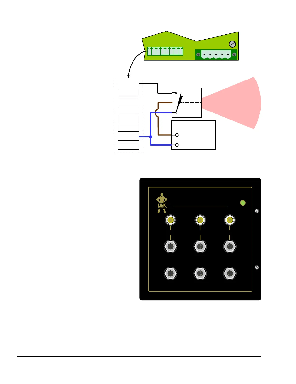
If more power is required for sensors,
then Figure 81 shows how an external
power supply can be connected for
additional sensor power.
Also note that if the System 2600 itself
is powered by +24VDC instead of
120VAC, then it can pass along 1 amp
to sensors.
Finally, perhaps the best and most flexible way to
connect the inputs is by way of using the Model
2620 Sensor Interface unit. This is a powered
connection box that can supply 0.5 amps to
sensors using its internal power supply or can pass
through up to 10 Amps of an external +24VDC
supply. It has 6 standard M12 sensor connectors
on its front and 3 banana jack / binding post
connectors for discrete sensor connections. It also
has options for standard or customer supplied
bulk connectors so that a single cable can be
plugged in from the die that connects all sensors
at once.
This interface comes standard with a six
conductor plus ground cable that is wired from the
output connector of the 2620 to GND and IN1 to
IN6 of the System 2600 die protection inputs
connector.
IN1
IN6
IN4
IN5
IN2
IN3
GND
NPN
BK
BN
BU
+Supply
-Supply
(common)
POWER SUPPLY
(Typically 24VDC)
Diffuse Reflective
Part Sensor
(NPN)
L1
L2
PE
+24
GND
IN1
IN2
IN3
IN4
IN5
IN6
GND
+24V
Die Protection
Inputs Connector
+24V
1 2 3 4 5 6 7 8
1
2
3
4
5
6
7
8
Figure 81: Die Protection Inputs Connection Wiring Example
with External Power Supply
MODEL 2620
SENSOR INTERFACE
POWER
LINK ELECTRIC & SAFETY CONTROL CO.
444 McNALLY DR. NASHVILLE, TN. 37211
Figure 82: Model 2620 Sensor Interface