Doc #: L-2600-1023 Page 6 Rev. 02
1 INTRODUCTION
The System 2600 is a
stand-alone die protection
and, optionally,
programmable limit switch
(PLS) unit that can be used
with any existing press
control. It serves two
primary purposes - die
protection and automation.
The die protection
capabilities of the System
2600 offer enough
flexibility to meet the needs
of almost any die protection
application.
The System 2600 features
six built-in die protection
channels which are
designed for use in
monitoring various material
and tool conditions that are important to the correct operation of the stamping process such as:
• Misfeed of the material (long feed, short feed, stock buckle)
• Verification of part ejection
• Stripper position
• Verification of slug ejection / detection of slug stacking
• End of stock
This is accomplished by installing appropriate sensors and probes in or near the die and connecting these
sensors to the die protection channel inputs of the operator terminal. The channels are then programmed
through the operator terminal to perform the desired monitoring function for the connected input. In the
event that improper conditions occur, the machine can be stopped, avoiding excessive delay in the
production process or damage to the tooling and/or press.
Either solid state (NPN or PNP) sensors or probes and mechanical sensors may be used to drive the
inputs. This is configurable on a per-channel and per-job basis so using a variety of sensors is a valid
option. Once configured, these settings will be automatically recalled with each job.
The System 2600 can be programmed to monitor each individual die protection input in the manner
necessary to ensure that the process is operating in the intended manner. Each channel can be
programmed to function as one of several logic types, which are covered in the configuration section.
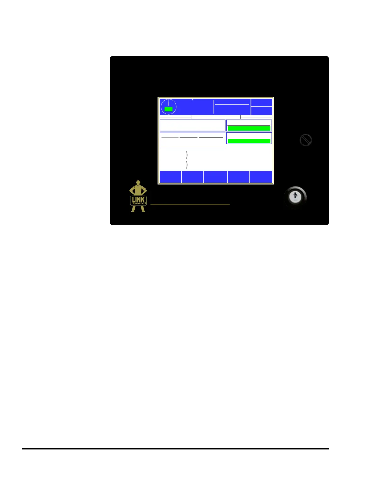
SYSTEM 2600
PLS/DIE PROTECTION
USE ONLY FINGERS TO OPERATE TOUCH SCREEN
LINK ELECTRIC & SAFETY CONTROL CO.
444
McNALLY DR. NASHVILLE, TN. 37211
359
TOP
Stroke Speed
0
SPM
Espanol
Diagnose
ACC
Reason for
the Last Stop
Running
Status
System 2600 Tonnage Monitor
Job: 1233
Lower Bracket
Die Protection
All Conditions OK
Counter
Count
Limit
Part
Batch
334
84
3000
250
Power Up
All Conditions OK
Mode: Production
Limit Switch
All Conditions OK