Doc #: L-2600-1023 Page 35 Rev. 02
The “State” of each input gives the operator general
information on the status of the die protection
channel. When no error is present on the channel, a
simple “On” or “Off” is displayed. When “On”, the
state is shown with a blue background to make the
difference between “On” and “Off” more obvious
from a distance. If the channel is bypassed, the
background will be yellow, and if the channel has
an error, the background will be red and there will
be an asterisk after “On” or “Off”.
Figure 25 shows an example of what the screen
would look like after channel 3, an “In Position”
sensor, fails to detect that the material is in place at
the end of the detection window. The “State” is
“Off*” with a red background. The “Ch. Status” for channel 3 gives the specific reason for the stop – in
this case “Not in position at end of window”. The “Module Status” indicated that at least one channel
has an error.
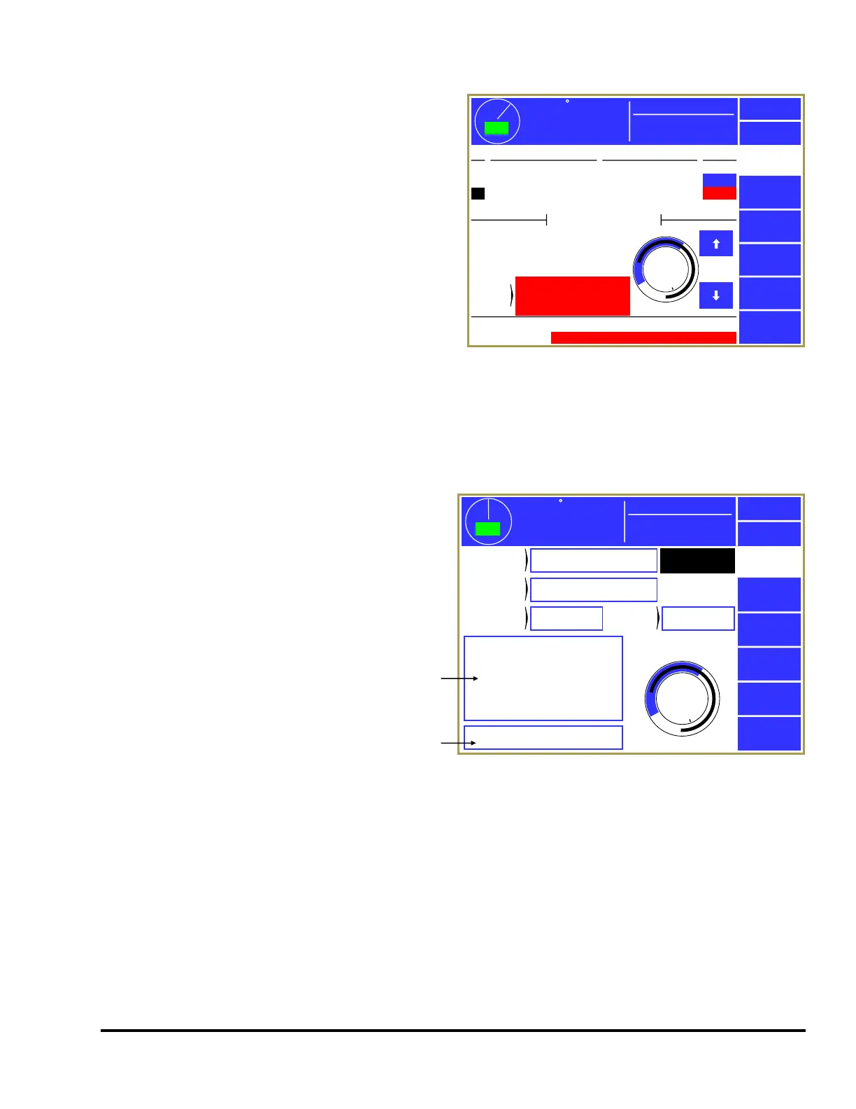
3.3.3 Die Protection Channel Settings Main Screen
If the Channel Settings softkey is pressed in
the Die Protection main screen (see Figure
24), the display will show a settings screen
for the currently selected channel that will
look something like Figure 26. The
appearance of this screen will vary
somewhat depending on the “Channel Type”
selected, as some types do not use some
settings.
The Previous Channel and Next Channel
softkeys can be used page through the
channels without going back to the Die
Protection main screen.
The blue arc in the circular angle display
shows the timing window that is set for the channel, assuming the “Channel Type” requires one. The
black arc in the circular angle display shows the actual angles where the sensor was “On” in the last full
stroke (0 to 359 degrees). This could be displayed as more than one arc if the sensor turns “On” in
multiple places in the stroke. The captured sensor angles are automatically updated every stroke.
42
TOP
Mode:
Production
Stroke Speed
0
SPM
ACC
Espanol
Exit
Die
Protection
Channel
Settings
Bypass
Diagnose
Reset
Ch Channel Type Description State
1
2
3
4
Static
Static
In Position
1 Part Detector Edge
Stock Buckle
End of Stock
Feed Complete
Part Detector
Off
On
Off*
Off
OIT Die Prot. Channel 3
Module Status:
0
270
180
90
Stop Type:
Bypassed:
Immediate
No
Ch.
Status
Not in position at end of
window
One or more channel errors
Figure 25: Die Protection Main Screen with Error
359
TOP
Stroke Speed
0
SPM
ACC
Espanol
Exit
Die
Protection
Previous
Channel
Next
Channel
0
270
180
90
Die Prot.
Channel 3
Channel
Type
In Position
Description
Feed Complete
Input
Type
Normally OFF
Sensor
Output
NPN (Sink)
Stop Type:
Bypassed:
Immediate
No
Window On at 240°, Off at 35°
Mode:
Production
a
b
Figure 26: Die Protection Channel Settings Screen