Doc #: L-2600-1023 Page 91 Rev. 02
7.5.8 Wiring Optional Limit Switch Modules
The System 2600 can
support 0, 4, or 8 limit
switch outputs as well as 0
or 4 configurable output
relays that support a variety
of signaling functions (see
section 4.10 on page 63 for
details). The relay modules
can be mounted in an
existing enclosure or
mounted in a Link supplied
enclosure with the same
dimensions as the System
2600 itself. The Link
supplied enclosure can hold
all three optional relay
modules
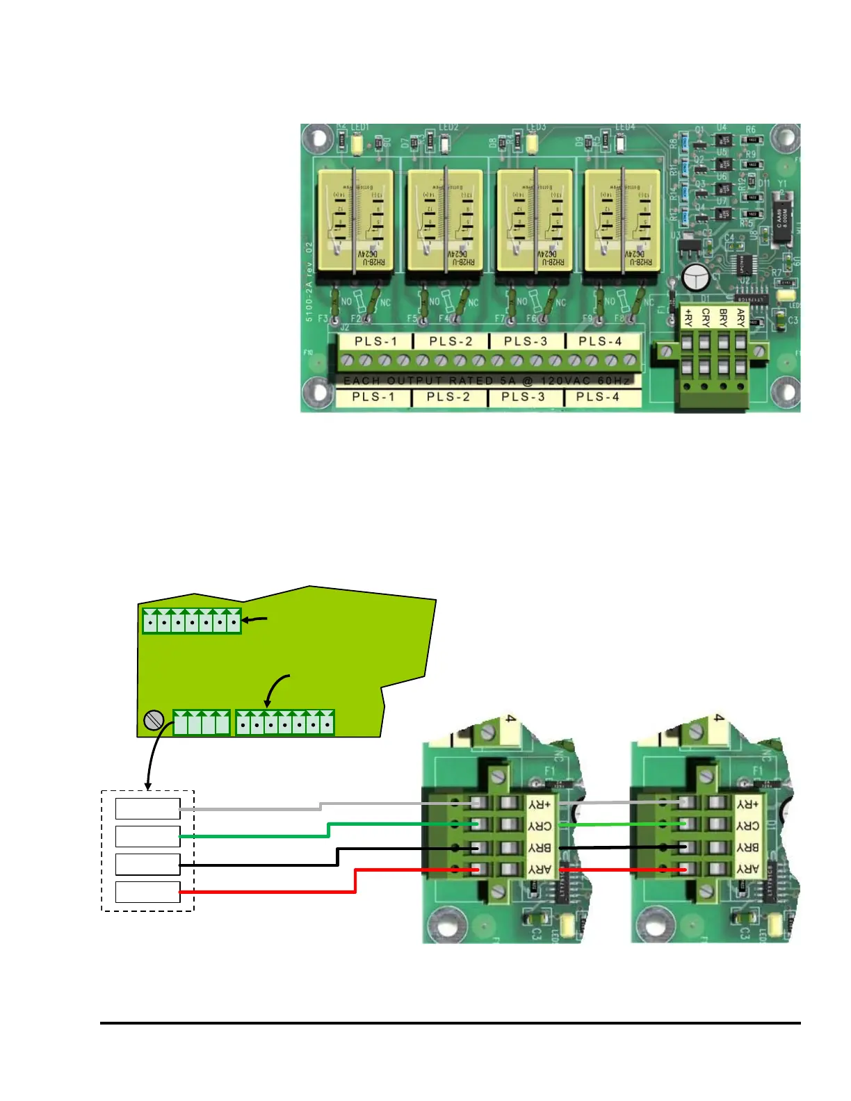
Figure 84 shows how to connect limit switch modules to the System 2600. The special double plugs on
the limit switch modules allow simple daisy chaining of the wiring from the System 2600 to the first
module, and then to the second and third modules, if used.
The order that the modules are connected is not important.
Figure 83: Electro-Mechanical Limit Switch Module
Auxiliary
Inputs
Connector
+24V
GND
I1
I2
I3
I4
I5
Encoder
Connector
+RY
ARY
CRY
BRY
Black
Red
Green
White
1
2
3
4
+24
-T
+T
+R
-R
GND
SLD
1 2 3 4
+RY
CRY
BRY
ARY
Limit Switch
Module 1 - 4
Limit Switch
Module 5 - 8
Figure 84: Limit Switch Module Wiring