Doc #: L-2600-1023 Page 63 Rev. 02
4.10 Output Relays Configuration
Two Programmable Limit Switch modules and one
programmable Output Relay module can be
optionally used with the System 2600. Each
module can provide 4 relays (1 normally open
contact and 1 normally open or normally closed
contact) or 4 solid state outputs (AC or DC) (see
section 7.5.8 on page 91 for connection
information).
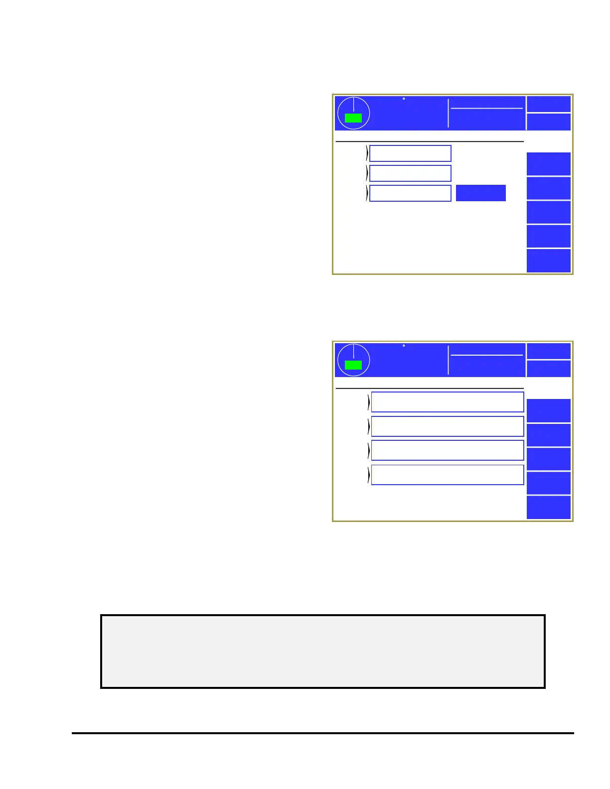
Press the Output Relays softkey in the main
configuration screen as shown in Figure 43 to
display the screens shown in Figure 54.
By pressing the blue bordered area next to each
group of potential relay modules, each module can
be configured to be “Not Installed” or “Installed”. Since Output Relays are optional, depending on
application, none or all modules may be installed for a given press.
When selected to “Installed”, the System 2600 will
monitor the relay drive signals for feedback
verification. A fault is generated if the feedback
signals do not track the intended state of the output.
A fault will occur if the relay module is configured
to “Installed” but is not physically installed, or if
there is a fault with the drive signal to the relay or
feedback signal from the relay. The fault must be
corrected and the Reset softkey pressed in order to
clear the error. If the output module uses electro-
mechanical relays (not solid state), this fault will
occur if the relay is removed from the socket or if a
problem exists with the coil of the relay.
If optional output relays OR 1-4 are installed, then a
Configure Functions softkey is shown just to the
right of its setting (as in the example of Figure 54) that will display a screen similar to Figure 55. This
allows the function of each output relay in that bank to be configured. Press inside the blue bordered
area next to each OR to bring up a list of functions to select from.
The full list of functions available for assignment to each output relay is listed in the table below.
359
TOP
Stroke Speed
0
SPM
ACC
Espanol
Exit
Output
Relays
PLS
1-4
PLS
5-8
OR
1-4
Installed
Installed
Installed
Configure
Functions
Mode: Production
Output Relay Boards Configuration
Figure 54: Output Relays Configuration Screen
359
TOP
Stroke Speed
0
SPM
ACC
Espanol
Exit
Output
Relays
OR 1
Function
1: ON if Die Protection Bypassed
Mode: Production
Output Relay Functions
OR 2
Function
7: ON if in Setup Mode
OR 3
Function
3: ON if Top Stop
OR 4
Function
6: ON if Any Stop or Inhibit
Figure 55: Output Relays Function Configuration
NOTE: A given output relay type can be configured on more than one output relay if
additional contacts of that type are needed. For instance, if more than one
piece of auxiliary equipment needs independent contacts that indicate the
system is in setup mode, then Type 7 could be selected for both “OR 1” and
“OR 2”.