Doc #: L-2600-1023 Page 33 Rev. 02
3.3.2 The Die Protection Main Screen
Pressing inside the blue bordered “Die
Protection” area on the Main Screen (see
Figure 8 on page 21) will cause the Die
Protection screen shown in Figure 24 to
be displayed.
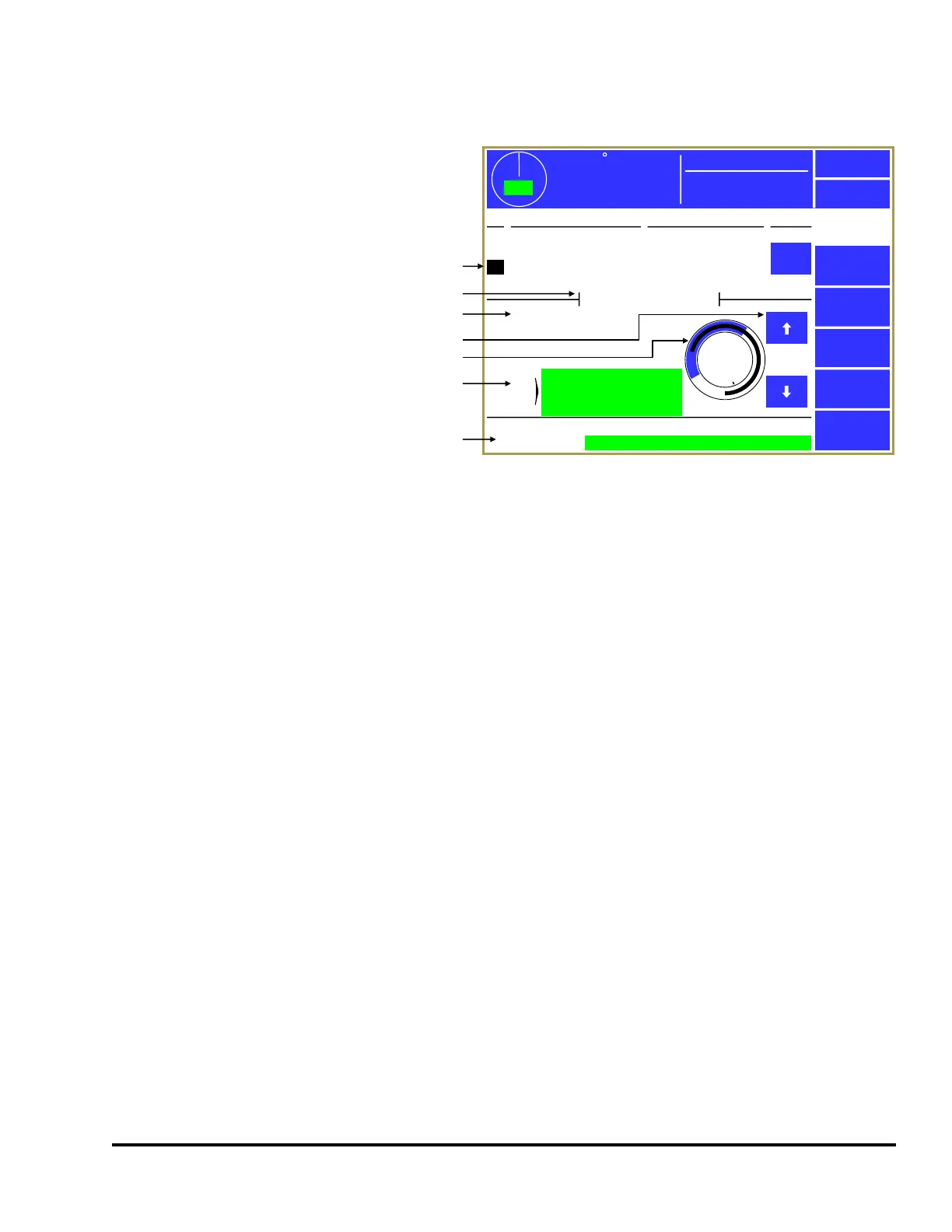
The upper half of the screen shows an
overview of up to four die protection
channels at a time. Channels 1 to 4 are
shown on the first page, and channels 5
and 6 are shown on the second. The
“Channel Type”, “Description”, and
“State” (On or Off) of each channel is
shown.
Next is an area that shows some more
specific configuration and diagnostic
data for the currently selected channel. The currently selected channel is designated by the highlighted
cursor on the channel number (in the example of Figure 24, channel 3 is currently selected. The up and
down arrow buttons to the right of the graphical circular angle display move the current channel
highlight cursor up and down. The specific information shown in this section will depend on the
“Channel Type” selected for the channel.
There are several softkeys on this screen that come into play at various times. The softkeys and other
functions of this screen are discussed in the following sections. Some softkeys may not be shown at
times depending on the RUN/PROG key position, whether the press is running, and other factors.
In Figure 24, the various parts of the screen are:
This area displays the channels (4 at a time) along with the channel type,
description, and whether the sensor is On or Off. Note in the example above
that channel 3 is highlighted and that the highlighted channel has additional
information shown in the bottom half of the screen. The Up and Down arrow
keys (pointed to by “d” in Figure 24) are used to move the highlighted cursor
This line shows which channel the information below it applies to. This is the
same as the channel which is highlighted by the channel cursor (shown by “a”
This area shows information on the particular settings that apply to the
channel type. This varies from type to type.
a
359
TOP
Mode:
Production
Stroke Speed
0
SPM
ACC
Espanol
Exit
Die
Protection
Channel
Settings
Bypass
Diagnose
Reset
Ch Channel Type Description State
1
2
3
4
Static
Static
In Position
1 Part Detector Edge
Stock Buckle
End of Stock
Feed Complete
Part Detector
Off
On
On
Off
OIT Die Prot. Channel 3
Module Status:
0
270
180
90
Stop Type:
Bypassed:
Immediate
No
Ch.
Status
OK
OK
b
c
d
e
f
g
Figure 24: Die Protection Main Screen