Doc #: L-2600-1023 Page 50 Rev. 02
3.5.1 Configuring Production Counters
Up to 2 counter groups can be enabled on a job by
job basis. In other words, one job can have one
counter group enabled, while a second job can have
2 counter groups enabled. Cycle based counter
groups can also be set to increment by a particular
value every so many cycles rather than
incrementing by 1. To configure the counters, press
the Counter Settings softkey in the counter screen of
Figure 37.
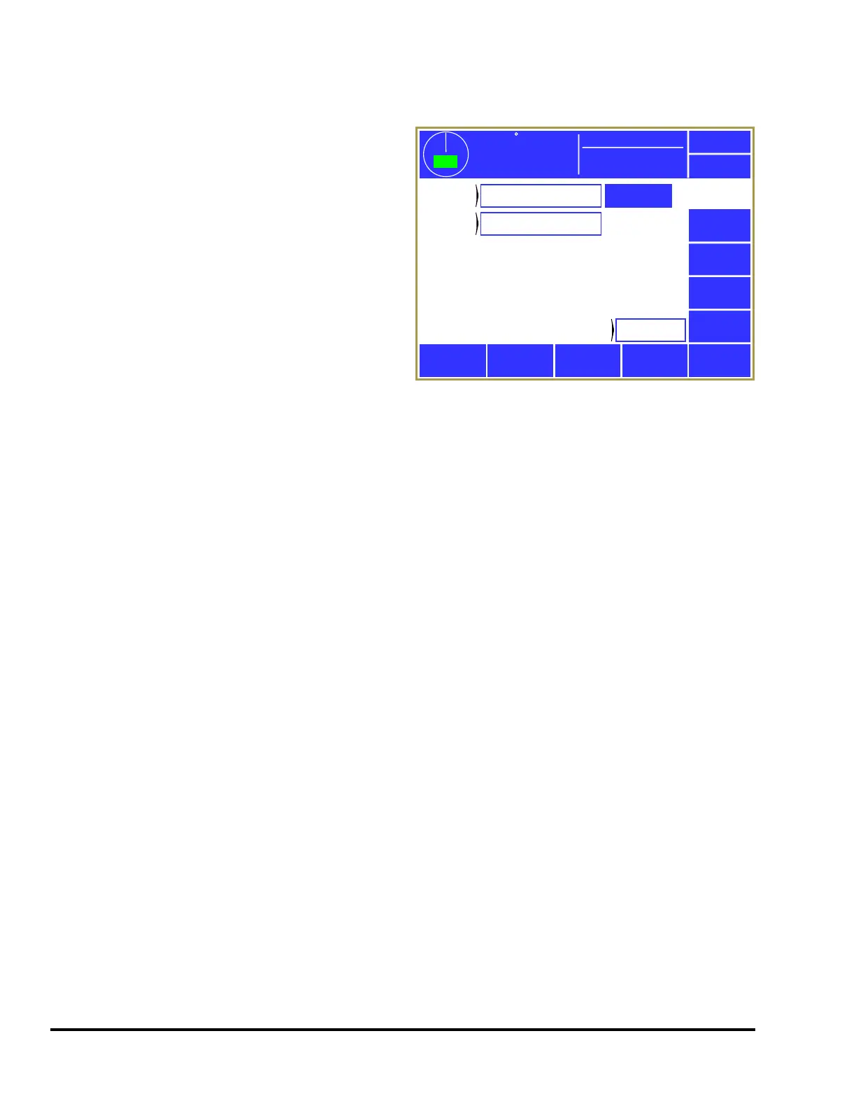
A screen similar to Figure 39 will appear and
allows each counter group to be set to cycle based
counting, sensor-based counting, or not used.
Hitting the Configure System softkey in this screen
will bring up a screen with three settings –
“Maximum Number of Counter Groups”, “Enable True (Sensor Based) Part Counters”, and “Count in
Setup Mode”. These settings apply to the system as a whole instead of to a job. The maximum number
of counter groups can be set to 1 to 2 and will affect how many counter groups are shown in the screen
of Figure 39. If “Enable True (Sensor Based) Part Counters” is set to “No”, then “Sensor Based” will
not be available to choose as counter group type. Both of these settings are present to allow a reduction
in the number of settings presented to operators for features that are not used. Finally, “Count in Setup
Mode” controls whether cycle based counters will count when a “setup mode” is active.
Counter groups that are set to “Cycle Based” also have a Configure button shown to the right of the
group (as seen in Figure 39 for Counter Group 1). When pressed, a screen will appear that allows the
“Counter Increment” and “Counter Frequency” to be set. The “Counter Increment” is how much the
counter will be increased when a count occurs. For instance, a job producing two parts per cycle would
count by 2 every 1 cycle. The “Counter Frequency” is how often the counter should count. A
lamination die might produce a part every 10 cycles. If a lamination die with 10 laminations was also a
2 out die, the “Counter Frequency” would be set to 10, and the “Counter Increment” would be set to 2.
The counter would then count by 2 every 10 cycles. For typical one-out jobs, both of these values
would be 1, which would count by 1 every 1 cycle.
If a counter group is set to “Sensor Based” then it is driven by one or more die protection inputs. For
those die protection channels types that have “Increment Counter” settings that are set to the counter
group, the counter will increment when the channel senses a part.
3.5.2 Production Counters
The three production counters provided are Part, Batch and Quality. All production counters that are
turned “On” will increment as the press strokes.
359
TOP
Stroke Speed
0
SPM
ACC
Espanol
Exit
Counters
Configure
Counter
Group 1
Cycle Based
Counter
Group 2
Sensor Based
Configure
System
Job Hit
Count
509
Mode:
Production
Figure 39: Counter Configuration Screen